- Engine coolant temperature 65°C (149°F), or lower (3 PTC heater relays operating)
- Engine coolant temperature 70°C (158°F), or lower (2 PTC heater relays operating)
- Engine coolant temperature 75°C (167°F), or lower (A PTC heater relay operating)
Lexus NX: PTC Heater Circuit
Lexus NX Service Manual / Vehicle Interior / Heating / Air Conditioning / Air Conditioning System / PTC Heater Circuit
DESCRIPTION
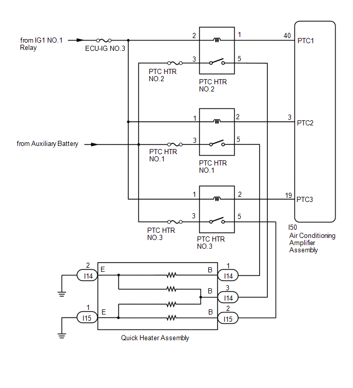
The air conditioning amplifier assembly sends operation signals to the PTC heater relays when quick heater assembly operation conditions are met. Based on the signals from the air conditioning amplifier assembly, the PTC heater relays turn on, and power is supplied to the quick heater assembly installed in the air conditioning radiator assembly.
Quick Heater Assembly Operation Condition| Control ECU | Condition |
|---|---|
| Air Conditioning Amplifier Assembly | Power switch on (READY) |
| Integration control and panel assembly (ECO mode switch) off | |
| Blower switch: on | |
| Temperature settings: MAX HOT | |
| IDH terminal signal less than 1 V (Inverter with converter assembly overload not detected) | |
| | |
| Ambient temperature 10°C (50°F) or lower |
WIRING DIAGRAM
CAUTION / NOTICE / HINT
NOTICE:
- Inspect the fuses for circuits related to this system before performing the following procedure.
-
If the auxiliary battery voltage is low, the PTC heater, seat heater system (w/ Seat Heater System) and climate control seat system (w/ Climate Control Seat System) may not operate. When "High Power Consumption Partial Limit On AC/Heater Operation." is displayed on the multi-information display in the combination meter assembly, inspect the auxiliary battery, referring to On-vehicle Inspection for the charging system.
Click here
.gif)
HINT:
If the auxiliary battery voltage is low, "Operation Limitation Control History Count (Level 1)" and "Operation Limitation Control History Count (Level 2) is counted.
Click here
-
If the auxiliary battery voltage is low, the PTC heater may not operate. Refer to Data List for the power steering system.
for Manual Tilt and Manual Telescopic Steering Column: Click here
for Power Tilt and Power Telescopic Steering Column: Click here
-
When the auxiliary battery is disconnected, or servo motor or the air conditioning amplifier assembly is replaced, be sure to perform servo motor initialization.
Click here
PROCEDURE
| 1. | PERFORM ACTIVE TEST USING TECHSTREAM |
(a) Connect the Techstream to the DLC3.
(b) Turn the power switch on (IG).
(c) Turn the Techstream on.
(d) Enter the following menus: Body Electrical / Air Conditioner / Active Test.
(e) Check the operation by referring to the table below.
Body Electrical > Air Conditioner > Active Test| Tester Display | Measurement Item | Control Range | Diagnostic Note |
|---|---|---|---|
| Heater Active Level | Quick heater assembly | Min.: 0, Max.: 3 | - |
| Tester Display |
|---|
| Heater Active Level |
OK:
Heater Active Level changes normally.
| NG | .gif) | PROCEED TO NEXT SUSPECTED AREA SHOWN IN PROBLEM SYMPTOMS TABLE |
|
.gif)
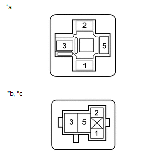
| 2. | INSPECT PTC HEATER RELAY (PTC HTR NO.1, PTC HTR NO.2, PTC HTR NO.3) |
(a) Remove the PTC heater relays.
(b) Inspect the PTC heater relays.
Click here
| NG | | REPLACE PTC HEATER RELAY |
|
| 3. | CHECK HARNESS AND CONNECTOR (PTC HEATER RELAY - BATTERY) |
| (a) Remove the PTC heater relays. |
|
(b) Measure the voltage according to the value(s) in the table below.
Standard Voltage:
PTC HTR NO.1
| Tester Connection | Switch Condition | Specified Condition |
|---|---|---|
| Relay terminal 3 - Body ground | Power switch off | 11 to 14 V |
| Relay terminal 1 - Body ground | Power switch off | Below 1 V |
| Relay terminal 1 - Body ground | Power switch on (IG) | 11 to 14 V |
PTC HTR NO.2
| Tester Connection | Switch Condition | Specified Condition |
|---|---|---|
| Relay terminal 3 - Body ground | Power switch off | 11 to 14 V |
| Relay terminal 2 - Body ground | Power switch off | Below 1 V |
| Relay terminal 2 - Body ground | Power switch on (IG) | 11 to 14 V |
PTC HTR NO.3
| Tester Connection | Switch Condition | Specified Condition |
|---|---|---|
| Relay terminal 3 - Body ground | Power switch off | 11 to 14 V |
| Relay terminal 1 - Body ground | Power switch off | Below 1 V |
| Relay terminal 1 - Body ground | Power switch on (IG) | 11 to 14 V |
| NG | | REPAIR OR REPLACE HARNESS OR CONNECTOR |
|
| 4. | CHECK HARNESS AND CONNECTOR (PTC HEATER RELAY - AIR CONDITIONING AMPLIFIER ASSEMBLY) |
(a) Remove the PTC heater relays.
(b) Disconnect the I50 air conditioning amplifier assembly connector.
(c) Measure the resistance according to the value(s) in the table below.
Standard Resistance:
PTC HTR NO.1
| Tester Connection | Condition | Specified Condition |
|---|---|---|
| Relay terminal 2 - I50-3 (PTC2) | Always | Below 1 Ω |
| Relay terminal 2 or I50-3 (PTC2)- Body ground | Always | 10 kΩ or higher |
PTC HTR NO.2
| Tester Connection | Condition | Specified Condition |
|---|---|---|
| Relay terminal 1 - I50-40 (PTC1) | Always | Below 1 Ω |
| Relay terminal 1 or I50-40 (PTC1) - Body ground | Always | 10 kΩ or higher |
PTC HTR NO.3
| Tester Connection | Condition | Specified Condition |
|---|---|---|
| Relay terminal 2 - I50-19 (PTC3) | Always | Below 1 Ω |
| Relay terminal 2 or I50-19 (PTC3) - Body ground | Always | 10 kΩ or higher |
| NG | | REPAIR OR REPLACE HARNESS OR CONNECTOR |
|
| 5. | CHECK HARNESS AND CONNECTOR (PTC HEATER RELAY - QUICK HEATER ASSEMBLY AND BODY GROUND) |
(a) Remove the PTC heater relays.
(b) Disconnect the I14 and I15 quick heater assembly connectors.
(c) Measure the resistance according to the value(s) in the table below.
Standard Resistance:
PTC HTR NO.1
| Tester Connection | Condition | Specified Condition |
|---|---|---|
| I14-1 (B) - Relay terminal 5 | Always | Below 1 Ω |
| I14-2 (E) - Body ground | Always | Below 1 Ω |
| I14-1 (B) or Relay terminal 5 - Body ground | Always | 10 kΩ or higher |
PTC HTR NO.2
| Tester Connection | Condition | Specified Condition |
|---|---|---|
| I14-3 (B) - Relay terminal 5 | Always | Below 1 Ω |
| I14-2 (E) - Body ground | Always | Below 1 Ω |
| I15-1 (E) - Body ground | Always | Below 1 Ω |
| I14-3 (B) or Relay terminal 5 - Body ground | Always | 10 kΩ or higher |
PTC HTR NO.3
| Tester Connection | Condition | Specified Condition |
|---|---|---|
| I15-2 (B) - Relay terminal 5 | Always | Below 1 Ω |
| I15-1 (E) - Body ground | Always | Below 1 Ω |
| I15-2 (B) or Relay terminal 5 - Body ground | Always | 10 kΩ or higher |
| NG | | REPAIR OR REPLACE HARNESS OR CONNECTOR |
|
| 6. | INSPECT QUICK HEATER ASSEMBLY |
(a) Remove the quick heater assembly.
Click here
(b) Inspect the quick heater assembly.
Click here
| OK | | REPLACE AIR CONDITIONING AMPLIFIER ASSEMBLY |
| NG | | REPLACE QUICK HEATER ASSEMBLY |
READ NEXT:
 Ambient Temperature Display System
DESCRIPTION The thermistor assembly (ambient temperature sensor) is installed in front of the cooler condenser assembly to detect the ambient temperature which is used to control the air conditioning
ECO Switch Circuit
DESCRIPTION When the integration control and panel assembly (ECO mode switch) is turned on, the air conditioning amplifier assembly receives an integration control and panel assembly (ECO mode switch)
IG Power Source Circuit
DESCRIPTION The main power source is supplied to the air conditioning amplifier assembly when the power switch is on (IG). The power is used for operating the air conditioning amplifier assembly, serv
SEE MORE:
Removal
REMOVAL PROCEDURE 1. PRECAUTION NOTICE: After turning the power switch is turned off, there may be a waiting time before disconnecting the auxiliary negative (-) battery terminal. Click here 2. CUSTOMIZE POWER TILT AND POWER TELESCOPIC STEERING COLUMN SYSTEM (a) Disable the auto tilt away function
Using the interior lights
Interior lights list
Location of the interior lights
Outer foot lights
Personal lights
Front interior light
Rear interior light
Footwell lights
When the power switch is in ON mode, the footwell lights will turn on.
However, if the instrument panel light control switch is tur
© 2016-2026 Copyright www.lexunx.com
