Lexus NX: Height Control Sensor
Components
COMPONENTS
ILLUSTRATION
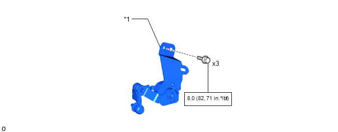
| *1 | REAR HEIGHT CONTROL SENSOR SUB-ASSEMBLY | - | - |
Removal
REMOVAL
PROCEDURE
1. REMOVE REAR HEIGHT CONTROL SENSOR SUB-ASSEMBLY
| (a) Disconnect the connector. |
|
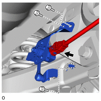
(b) Remove the 3 bolts.
(c) Detach the hook and remove the rear height control sensor sub-assembly.
NOTICE:
If the rear height control sensor sub-assembly has been dropped, replace it with a new one.
Inspection
INSPECTION
PROCEDURE
1. INSPECT REAR HEIGHT CONTROL SENSOR SUB-ASSEMBLY LH
(a) Check the rear height control sensor sub-assembly LH.
(1) Connect 3 dry batteries of 1.5 V in series.
(2) Connect the positive (+) end of the batteries to terminal 3 (SHB) of the rear height control sensor sub-assembly LH and the negative (-) end of the batteries to terminal 1 (SHG). While slowly moving the sensor link up and down, measure the voltage between terminal 2 (SHRR) and terminal 1 (SHG).
NOTICE:
- Do not use rechargeable batteries as they may not output a voltage of 1.5 V.
- Do not apply a voltage of more than 6 V.
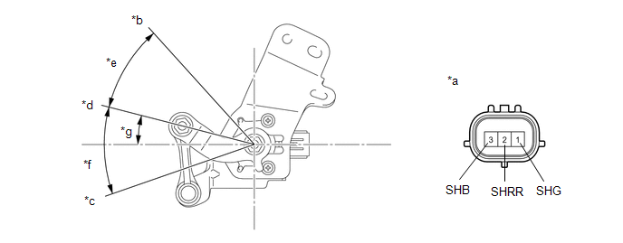
| *a | Component without harness connected (Rear Height Control Sensor Sub-assembly LH) | *b | Low |
| *c | Standard Position | *d | High |
| *e | -45° | *f | 12° |
| *g | +45° | - | - |
(3) Measure the voltage according to the value(s) in the table below.
Standard Voltage:
| Tester Connection | Condition | Specified Condition |
|---|---|---|
| 2 (SHRR) - 1 (SHG) | +45° (High) | Approx. 4.5 V |
| 0° (Standard position) | Approx. 2.25 V | |
| -45° (Low) | Approx. 0.5 V |
If the result is not as specified, replace the rear height control sensor sub-assembly LH.
Installation
INSTALLATION
PROCEDURE
1. INSTALL REAR HEIGHT CONTROL SENSOR SUB-ASSEMBLY
NOTICE:
If the rear height control sensor sub-assembly has been dropped, replace it with a new one.
(a) Attach the hook to install the rear height control sensor sub-assembly.
(b) Install the 3 bolts.
Torque:
8.5 N·m {87 kgf·cm, 75 in·lbf}
(c) Connect the connector.
2. PERFORM INITIALIZATION
NOTICE:
If any of the work in the table below has been performed, vehicle information registration and initialization of the headlight ECU sub-assembly LH is necessary.
Click here .gif)
| Performed Work or System Condition | Necessary Procedures |
|---|---|
| Work that changes the vehicle height such as replacement or removal/installation of the rear height control sensor sub-assembly LH or replacement of suspension components | Initialization of the headlight ECU sub-assembly LH |
3. INSPECT AUTOMATIC LIGHT CONTROL SYSTEM
Click here
4. INSPECT HEADLIGHT AIMING
for Single Beam Headlight:
Click here
for Triple Beam Headlight:
Click here
READ NEXT:
 High Mounted Stop Light Assembly
ComponentsCOMPONENTS ILLUSTRATION *1 CENTER STOP LIGHT ASSEMBLY *2 REAR SPOILER ASSEMBLY RemovalREMOVAL PROCEDURE 1. REMOVE REAR SPOILER ASSEMBLY Click here 2. REMOVE CENTER STOP LIGH
Components
COMPONENTS ILLUSTRATION *A w/o Power Back Door System *B w/ Power Back Door System *1 BACK DOOR FINISH COVER LH *2 BACK DOOR FINISH COVER RH *3 BACK DOOR LOCK COVER *4 BA
SEE MORE:
Removal
REMOVAL CAUTION / NOTICE / HINT NOTICE:
Do not replace the spiral cable with the battery connected and the power switch on (IG).
Do not rotate the spiral cable when the following conditions are met: 1) The steering wheel is removed, 2) the battery is connected, and 3) thepower switch on (IG).
Removal
REMOVAL CAUTION / NOTICE / HINT HINT:
Use the same procedure for the RH and LH sides.
The procedure described below is for the LH side.
PROCEDURE 1. REMOVE OUTER MIRROR LH Click here 2. REMOVE OUTER MIRROR COVER LH (a) Detach the 6 claws and 2 guides and remove the outer mirror cover L
