Lexus NX: Horn
Components
COMPONENTS
ILLUSTRATION
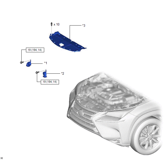
| *1 | HIGH PITCHED HORN ASSEMBLY | *2 | LOW PITCHED HORN ASSEMBLY |
| *3 | RADIATOR SUPPORT OPENING COVER | - | - |
.png) | N*m (kgf*cm, ft.*lbf): Specified torque | - | - |
Removal
REMOVAL
PROCEDURE
1. REMOVE RADIATOR SUPPORT OPENING COVER
Click here .gif)
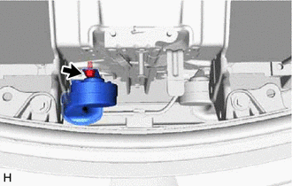
2. REMOVE HIGH PITCHED HORN ASSEMBLY
(a) Disconnect the connector.
| (b) Remove the bolt and high pitched horn assembly. |
|
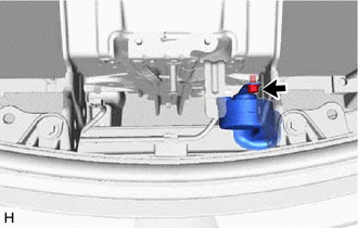
3. REMOVE LOW PITCHED HORN ASSEMBLY
(a) Disconnect the connector.
| (b) Remove the bolt and low pitched horn assembly. |
|
Inspection
INSPECTION
PROCEDURE
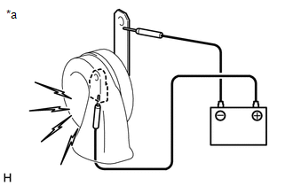
1. INSPECT HIGH PITCHED HORN ASSEMBLY
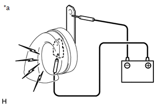
| *a | Component without harness connected (High Pitched Horn Assembly) |
(a) Apply battery voltage and check operation of the high pitched horn according to the table below.
OK:
| Measurement Condition | Specified Condition |
|---|---|
| Battery positive (+) → Terminal 1 Battery negative (-) → Horn body | High pitched horn sounds |
If the result is not as specified, replace the high pitched horn assembly.
2. INSPECT LOW PITCHED HORN ASSEMBLY
| *a | Component without harness connected (Low Pitched Horn Assembly) |
(a) Apply battery voltage and check operation of the low pitched horn according to the table below.
OK:
| Measurement Condition | Specified Condition |
|---|---|
| Battery positive (+) → Terminal 1 Battery negative (-) → Horn body | Low pitched horn sounds |
If the result is not as specified, replace the low pitched horn assembly.
READ NEXT:
 Horn System
Parts LocationPARTS LOCATION ILLUSTRATION *1 LOW PITCHED HORN ASSEMBLY *2 HIGH PITCHED HORN ASSEMBLY *3 HORN RELAY *4 SPIRAL CABLE SUB-ASSEMBLY *5 STEERING PAD SWITCH ASSEMB
Relay
On-vehicle InspectionON-VEHICLE INSPECTION PROCEDURE 1. INSPECT HORN RELAY ASSEMBLY (a) Remove the horn relay assembly. (b) Measure the resistance according to the value(s) in the tabl
SEE MORE:
Driver Side Door ECU Communication Stop (B2321)
DESCRIPTION This DTC is stored when LIN communication between the front power window regulator motor assembly LH and main body ECU (multiplex network body ECU) stops for 10 seconds or more. DTC No. Detection Item DTC Detection Condition Trouble Area B2321 Driver Side Door ECU Communic
Removal
REMOVAL PROCEDURE 1. PRECAUTION NOTICE: After turning the power switch is turned off, there may be a waiting time before disconnecting the auxiliary negative (-) battery terminal. Click here 2. CUSTOMIZE POWER TILT AND POWER TELESCOPIC STEERING COLUMN SYSTEM (a) Disable the auto tilt away function
