Lexus NX: Horn System
Parts Location
PARTS LOCATION
ILLUSTRATION
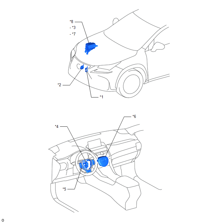
| *1 | LOW PITCHED HORN ASSEMBLY | *2 | HIGH PITCHED HORN ASSEMBLY |
| *3 | HORN RELAY | *4 | SPIRAL CABLE SUB-ASSEMBLY |
| *5 | STEERING PAD SWITCH ASSEMBLY | *6 | HORN BUTTON ASSEMBLY |
| *7 | HORN FUSE | *8 | NO. 2 ENGINE ROOM RELAY BLOCK |
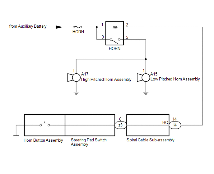
System Diagram
SYSTEM DIAGRAM
Problem Symptoms Table
PROBLEM SYMPTOMS TABLE
HINT:
Use the table below to help determine the cause of problem symptoms. If multiple suspected areas are listed, the potential causes of the symptoms are listed in order of probability in the "Suspected Area" column of the table. Check each symptom by checking the suspected areas in the order they are listed. Replace parts as necessary.
Horn System| Symptom | Suspected Area | Link |
|---|---|---|
| Horn does not sound | HORN fuse | - |
| HORN relay | | |
| Low pitched horn assembly | | |
| High pitched horn assembly | | |
| Steering pad switch assembly | | |
| Spiral cable sub-assembly | | |
| Horn button assembly | | |
| Harness or connector | - |
.gif)
READ NEXT:
 Relay
Relay
On-vehicle InspectionON-VEHICLE INSPECTION PROCEDURE 1. INSPECT HORN RELAY ASSEMBLY (a) Remove the horn relay assembly. (b) Measure the resistance according to the value(s) in the tabl
SEE MORE:
Seat Heater for Rear Left Seat does not Operate
DESCRIPTION When the refreshing seat switch is operated, the air conditioning amplifier assembly receives the signal via the LIN communication line, and operates the seat heater for the corresponding rear seat. WIRING DIAGRAM CAUTION / NOTICE / HINT NOTICE:
If the auxiliary battery voltage is l
System Diagram
SYSTEM DIAGRAM
