Lexus NX: Components
COMPONENTS
ILLUSTRATION
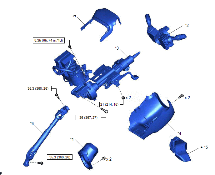
| *1 | COLUMN HOLE COVER SILENCER SHEET | *2 | COMBINATION SWITCH ASSEMBLY WITH SPIRAL CABLE SUB-ASSEMBLY |
| *3 | ELECTRIC POWER STEERING COLUMN SUB-ASSEMBLY | *4 | LOWER STEERING COLUMN COVER |
| *5 | NO. 1 AIR DUCT | *6 | NO. 2 STEERING INTERMEDIATE SHAFT ASSEMBLY |
| *7 | UPPER STEERING COLUMN COVER | - | - |
.png) | N*m (kgf*cm, ft.*lbf): Specified torque | ● | Non-reusable part |
ILLUSTRATION
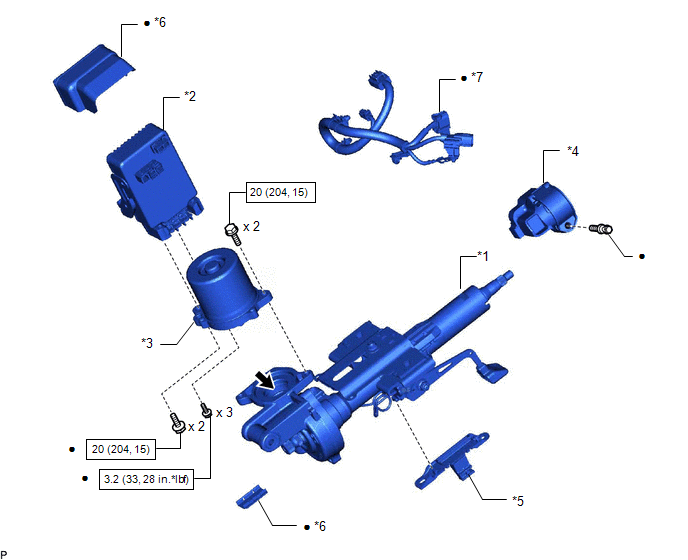
| *1 | ELECTRIC POWER STEERING COLUMN SUB-ASSEMBLY | *2 | POWER STEERING ECU ASSEMBLY |
| *3 | POWER STEERING MOTOR ASSEMBLY | *4 | STEERING LOCK ACTUATOR ASSEMBLY |
| *5 | WIRE HARNESS BRACKET | *6 | POWER STEERING ECU PROTECTOR |
| *7 | ECU WIRE SUB-ASSEMBLY | - | - |
| | N*m (kgf*cm, ft.*lbf): Specified torque | ● | Non-reusable part |
 | GREASE | - | - |
READ NEXT:
 Removal
REMOVAL CAUTION / NOTICE / HINT NOTICE:
Do not replace the spiral with sensor cable sub-assembly with the battery connected and the engine switch on (IG).
Do not rotate the spiral with sensor cab
Disassembly
DISASSEMBLY CAUTION / NOTICE / HINT NOTICE:
When using a vise, place aluminum plates between the part and vise.
When using a vise, do not overtighten it.
PROCEDURE 1. REMOVE STEERING LOCK ACTU
Inspection
INSPECTION CAUTION / NOTICE / HINT NOTICE:
When using a vise, place aluminum plates between the part and vise.
When using a vise, do not overtighten it.
PROCEDURE 1. INSPECT ELECTRIC POWER STE
SEE MORE:
Fail-safe Chart
FAIL-SAFE CHART FAIL-SAFE FUNCTION (a) When communication fails in any of the CAN bus wires (communication wires), a fail-safe function(s) operates. The fail-safe function that is specified for each system operates to prevent those systems from malfunctioning. (b) Effects on each system when communi
Performance Damper
ComponentsCOMPONENTS ILLUSTRATION *1 SUSPENSION TOWER DAMPER - - N*m (kgf*cm, ft.*lbf): Specified torque - - RemovalREMOVAL PROCEDURE 1. REMOVE WINDSHIELD WIPER MOTOR ASSEMBLY Click here 2. REMOVE SUSPENSION TOWER DAMPER (a) Remove the 2 nuts and the suspension tower d
© 2016-2026 Copyright www.lexunx.com
