Lexus NX: System Diagram
Lexus NX Service Manual / Engine & Hybrid System / 2ar-fxe (engine Control) / Ignition System / System Diagram
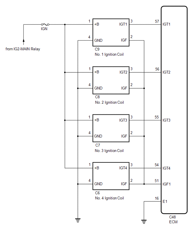
SYSTEM DIAGRAM
READ NEXT:
 On-vehicle Inspection
ON-VEHICLE INSPECTION CAUTION / NOTICE / HINT HINT: Perform "Inspection After Repair" after replacing an ignition coil assembly or spark plug. Click here PROCEDURE 1. PERFORM SPARK TEST (a) Check fo
Knock Sensor
ComponentsCOMPONENTS ILLUSTRATION *1 KNOCK CONTROL SENSOR - - N*m (kgf*cm, ft.*lbf) : Specified torque - - RemovalREMOVAL PROCEDURE 1. REMOVE INTAKE MANIFOLD Click here 2
Manifold Absolute Pressure Sensor
ComponentsCOMPONENTS ILLUSTRATION *1 MANIFOLD ABSOLUTE PRESSURE SENSOR *2 VACUUM HOSE N*m (kgf*cm, ft.*lbf): Specified torque - - On-vehicle InspectionON-VEHICLE INSPECTION P
SEE MORE:
IG Power Supply Voltage (C1551)
DESCRIPTION The power steering ECU assembly distinguishes the power switch status as on (IG) or off through the IG power source circuit. DTC No. Detection Item DTC Detection Condition Trouble Area Warning Indicate Return-to-normal Condition Note C1551 IG Power Supply Voltage I
Diagnostic Trouble Code Chart
DIAGNOSTIC TROUBLE CODE CHART Wireless Door Lock Control System DTC No. Detection Item Link B1242 Wireless Door Lock Tuner Circuit Malfunction
© 2016-2026 Copyright www.lexunx.com
