Lexus NX: Removal
REMOVAL
PROCEDURE
1. REMOVE DOOR SCUFF PLATE ASSEMBLY LH
Click here .gif)
2. REMOVE COWL SIDE TRIM BOARD LH
Click here
3. REMOVE INSTRUMENT SIDE PANEL LH
Click here
4. REMOVE NO. 1 INSTRUMENT PANEL SAFETY PAD SUB-ASSEMBLY
Click here
5. REMOVE REAR CONSOLE ARMREST ASSEMBLY
Click here
6. REMOVE UPPER NO. 2 CONSOLE PANEL GARNISH
Click here
7. REMOVE NO. 1 INSTRUMENT PANEL UNDER COVER SUB-ASSEMBLY
Click here
8. REMOVE LOWER NO. 1 INSTRUMENT PANEL FINISH PANEL
Click here
9. REMOVE STOP LIGHT CONTROL ECU ASSEMBLY
| (a) Disconnect the connector. |
|
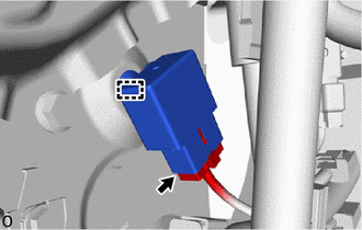
(b) Detach the clamp and remove the stop light control ECU assembly.
READ NEXT:
 Installation
INSTALLATION PROCEDURE 1. INSTALL STOP LIGHT CONTROL ECU ASSEMBLY (a) Attach the clamp to install the stop light control ECU assembly. (b) Connect the connector. 2. INSTALL LOWER NO. 1 INSTRUMENT PANE
Components
COMPONENTS ILLUSTRATION *1 COWL SIDE TRIM BOARD LH *2 DOOR SCUFF PLATE ASSEMBLY LH *3 NO. 1 INSTRUMENT PANEL UNDER COVER SUB-ASSEMBLY *4 STOP LIGHT SWITCH ASSEMBLY *5 STOP LI
SEE MORE:
Removal
REMOVAL CAUTION / NOTICE / HINT PROCEDURE 1. REMOVE ELECTRIC POWER STEERING COLUMN SUB-ASSEMBLY Click here 2. REMOVE POWER STEERING ECU ASSEMBLY (a) Detach the claw and remove the power steering ECU protector from the power steering ECU assembly. (b) Remove the 2 cable ties and h
Components
COMPONENTS ILLUSTRATION *1 DECK FLOOR BOX LH *2 NO. 3 DECK BOARD SUB-ASSEMBLY *3 REAR DECK FLOOR BOX *4 AUXILIARY BATTERY NEGATIVE TERMINAL N*m (kgf*cm, ft.*lbf): Specified torque - - ILLUSTRATION *1 FRONT SEAT ASSEMBLY LH *2 FRONT SEAT HEADREST ASSEMBLY
© 2016-2026 Copyright www.lexunx.com
