Lexus NX: Illumination for Panel Switch does not Come on with Tail Switch ON
CAUTION / NOTICE / HINT
NOTICE:
When replacing the radio receiver assembly, always replace it with a new one.
If a radio receiver assembly which was installed to another vehicle is used, the following may occur:
- A communication malfunction DTC may be stored.
- The radio receiver assembly may not operate normally.
HINT:
Depending on the parts that are replaced during vehicle inspection or maintenance, performing initialization, registration or calibration may be needed. Refer to Precaution for Audio and Visual System.
Click here .gif)
PROCEDURE
| 1. | CHECK VEHICLE SIGNAL (OPERATION CHECK) |
| (a) Enter the "Vehicle Signal Check Mode" screen. Refer to Check Vehicle Signal in Operation Check. Click here |
|
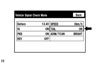
(b) Check that the display for "TAIL" changes between ON and OFF according to the light control switch operation.
OK:
| Light Control Switch | Display |
|---|---|
| Tail or head | ON |
| Off or AUTO | OFF |
HINT:
- This display is updated once per second. As a result, it is normal for the display to lag behind the actual switch operation.
- Make sure to move the vehicle to a bright area before performing an operation check with the light control switch in the AUTO position.
| OK | .gif) | REPLACE RADIO RECEIVER ASSEMBLY |
| NG | | PROCEED TO NEXT SUSPECTED AREA SHOWN IN PROBLEM SYMPTOMS TABLE |
READ NEXT:
 Display does not Dim when Light Control Switch is Turned ON
DESCRIPTION If the audio and visual system is turned on with the light control switch in the tail or head position, before AVC-LAN communication is established, the multi-display assembly dims accordi
Panel Switches do not Function
CAUTION / NOTICE / HINT NOTICE: When replacing the radio receiver assembly, always replace it with a new one. If a radio receiver assembly which was installed to another vehicle is used, the following
Screen Flicker or Color Distortion
PROCEDURE 1. CHECK DISPLAY SETTING (a) Reset display settings (contrast, brightness) and check that the screen appears normal. OK: The display returns to normal. OK END (DISPLAY SETTIN
SEE MORE:
MOST Communication Malfunction (B15D0)
DESCRIPTION Navigation system components communicate with each other via MOST communication. If a line short or short to ground occurs in a MOST communication line, communication will not be possible and the navigation system will not operate normally. After the power switch is turned on (ACC), if t
Installation
INSTALLATION CAUTION / NOTICE / HINT HINT:
Use the same procedure for the RH and LH sides.
The procedure listed below is for the LH side.
PROCEDURE 1. INSTALL FRONT NO. 1 SPEAKER ASSEMBLY NOTICE: Do not touch the cone part of the speaker. (a) Temporarily install the speaker by attaching t
