Lexus NX: Installation
Lexus NX Service Manual / Audio & Visual & Telematics / Audio / Video / Front Door Speaker / Installation
INSTALLATION
CAUTION / NOTICE / HINT
HINT:
- Use the same procedure for the RH and LH sides.
- The procedure listed below is for the LH side.
PROCEDURE
1. INSTALL FRONT NO. 1 SPEAKER ASSEMBLY
NOTICE:
Do not touch the cone part of the speaker.
| (a) Temporarily install the speaker by attaching the claw of the speaker to the door panel. |
|
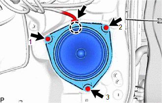
(b) Install the front No. 1 speaker assembly with the 3 screws.
HINT:
Tighten the screws in the order shown in the illustration.
(c) Connect the connector.
2. INSTALL FRONT DOOR TRIM BOARD SUB-ASSEMBLY LH
Click here .gif)
3. INSTALL POWER WINDOW REGULATOR MASTER SWITCH ASSEMBLY WITH FRONT DOOR ARMREST BASE PANEL
Click here
4. INSTALL FRONT DOOR INSIDE HANDLE BEZEL PLUG LH
Click here
5. INSTALL FRONT DOOR TRIM COVER LH
Click here
READ NEXT:
 Components
COMPONENTS ILLUSTRATION *A for 8 Speakers *B for 10 Speakers *C for 14 Speakers - - *1 FRONT DOOR OPENING TRIM WEATHERSTRIP LH *2 FRONT NO. 2 SPEAKER ASSEMBLY *3 FR
Removal
REMOVAL CAUTION / NOTICE / HINT HINT:
Use the same procedure for the RH and LH sides.
The procedure listed below is for the LH side.
PROCEDURE 1. REMOVE FRONT DOOR OPENING TRIM WEATHERSTRIP LH
SEE MORE:
On-vehicle Inspection
ON-VEHICLE INSPECTION PROCEDURE 1. INSPECT FOR COOLANT LEAK (for Inverter Coolant) (a) Remove the inverter reserve tank cap. CAUTION: To avoid the danger of being burned, do not remove the inverter reserve tank cap while the coolant for the inverter is still hot. (b) Install a radiator cap tester
Components
COMPONENTS ILLUSTRATION *1 DECK FLOOR BOX LH *2 NO. 3 DECK BOARD SUB-ASSEMBLY *3 REAR DECK FLOOR BOX *4 NEGATIVE AUXILIARY BATTERY TERMINAL N*m (kgf*cm, ft.*lbf): Specified torque - - ILLUSTRATION *1 DECK BOARD ASSEMBLY *2 DECK FLOOR BOX RH *3 NO. 1
© 2016-2026 Copyright www.lexunx.com
