Lexus NX: Indicator Circuit
DESCRIPTION
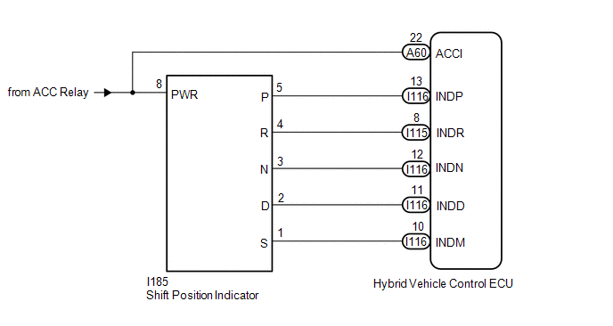
In accordance with the shift lever position, each shift position indicator light will turn on.
WIRING DIAGRAM
PROCEDURE
| 1. | CHECK SHIFT POSITION INDICATOR |
(a) Turn the power switch on (ACC).
(b) Check that each shift position indicator light turns on correctly.
| Result | Proceed to |
|---|---|
| All shift position indicator lights turn on simultaneously | A |
| Shift position indicator lights other than corresponding one turn on | A |
| Corresponding shift position indicator light does not turn on | B |
| No shift position indicator lights turn on | B |
(c) Turn the power switch off.
| B | .gif) | GO TO STEP 3 |
|
.gif)
| 2. | CHECK HARNESS AND CONNECTOR (CHECK FOR SHORT TO GND) |
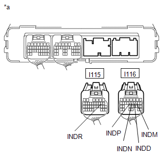
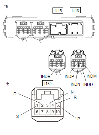
(a) Disconnect the I115 and I116 hybrid vehicle control ECU connectors.
| (b) Measure the resistance according to the value(s) in the table below. Standard Resistance:
|
|
(c) Reconnect the I115 and I116 hybrid vehicle control ECU connectors.
| OK | | REPLACE HYBRID VEHICLE CONTROL ECU |
| NG | | GO TO STEP 6 |
| 3. | CHECK HARNESS AND CONNECTOR (POWER SOURCE CIRCUIT) |
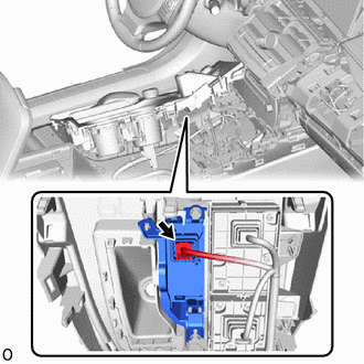
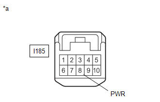
| (a) Disconnect the I185 shift position indicator connector. |
|
(b) Turn the power switch on (ACC).
| (c) Measure the voltage according to the value(s) in the table below. Standard Voltage:
|
|
(d) Turn the power switch off.
(e) Reconnect the I185 shift position indicator connector.
| NG | | REPAIR OR REPLACE POWER SOURCE CIRCUIT |
|
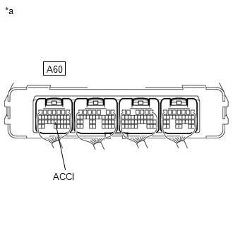
| 4. | CHECK HARNESS AND CONNECTOR (POWER SOURCE TERMINAL ACCI) |
(a) Turn the power switch on (ACC).
| (b) Measure the voltage according to the value(s) in the table below. Standard Voltage:
|
|
(c) Turn the power switch off.
| NG | | REPAIR OR REPLACE POWER SOURCE CIRCUIT |
|
| 5. | CHECK HARNESS AND CONNECTOR (CHECK FOR OPEN) |
(a) Disconnect the I115 and I116 hybrid vehicle control ECU connectors.
(b) Turn the power switch on (ACC).
| (c) Measure the voltage according to the value(s) in the table below. Standard Voltage:
|
|
(d) Turn the power switch off.
(e) Reconnect the I115 and I116 hybrid vehicle control ECU connectors.
| OK | | REPLACE HYBRID VEHICLE CONTROL ECU |
| NG | | GO TO STEP 7 |
| 6. | CHECK HARNESS AND CONNECTOR (HYBRID VEHICLE CONTROL ECU - SHIFT POSITION INDICATOR) |
(a) Disconnect the I115 and I116 hybrid vehicle control ECU connectors.
| (b) Disconnect the I185 shift position indicator connector. |
|
| (c) Measure the resistance according to the value(s) in the table below. Standard Resistance:
|
|
(d) Reconnect the I185 shift position indicator connector.
(e) Reconnect the I115 and I116 hybrid vehicle control ECU connectors.
| OK | | REPLACE SHIFT POSITION INDICATOR |
| NG | | REPAIR OR REPLACE HARNESS OR CONNECTOR |
| 7. | CHECK HARNESS AND CONNECTOR (HYBRID VEHICLE CONTROL ECU - SHIFT POSITION INDICATOR) |
(a) Disconnect the I115 and I116 hybrid vehicle control ECU connectors.
(b) Disconnect the I185 shift position indicator connector.
| (c) Measure the resistance according to the value(s) in the table below. Standard Resistance:
|
|
(d) Reconnect the I185 shift position indicator connector.
(e) Reconnect the I115 and I116 hybrid vehicle control ECU connectors.
| OK | | REPLACE SHIFT POSITION INDICATOR |
| NG | | REPAIR OR REPLACE HARNESS OR CONNECTOR |
READ NEXT:
 Drive Start Control System
DESCRIPTION The drive start control is controlled by the hybrid vehicle control ECU. If the hybrid vehicle control ECU determines that the shift lever and accelerator pedal are operated abnormally, dr
ECU Power Source Circuit
DESCRIPTION If the power switch is on (IG), the hybrid vehicle control ECU applies current to the MREL terminal to turn the IGCT relay on. This supplies power to the +B1 and +B2 terminals. WIRING DIAG
Motor Resolver Circuit
DESCRIPTION The cause of this malfunction may be the motor resolver. Check the motor resolver internal resistance and the connection condition from the inverter to the resolver. Related Parts Check
SEE MORE:
Problem Symptoms Table
PROBLEM SYMPTOMS TABLE NOTICE: If the headlight ECU sub-assembly LH has been replaced, it is necessary to synchronize the vehicle information and initialize the headlight ECU sub-assembly LH. Click here HINT: Use the table below to help determine the cause of problem symptoms. If multiple suspecte
Terminals Of Ecu
TERMINALS OF ECU HEADUP DISPLAY (METER MIRROR SUB-ASSEMBLY) (a) Measure the voltage and resistance according to the value(s) in the table below. Terminal No. (Symbol) Wiring Color Terminal Description Condition Specified Condition J5-1 (IG) - Body ground B - Body ground Power swi
