- Initialization procedure for when a power window regulator motor assembly has been removed/installed or a door glass and/or door glass run etc. have been removed/installed or replaced with new ones
- Initialization procedure for when the window cannot fully open via a down operation (door glass remains visible)
- Initialization procedure for when the door glass cannot fully close (erroneously operates in reverse) after initialization
- Initialization procedure for when the door glass cannot fully open (erroneously stops) after initialization
- Initialization procedure for when instructions to perform initialization appear in other troubleshooting flowcharts
Lexus NX: Initialization
Lexus NX Service Manual / Vehicle Exterior / Window / Glass / Power Window Control System / Initialization
INITIALIZATION
INITIALIZE POWER WINDOW CONTROL SYSTEM (ALL DOORS)
NOTICE:
- When a door window regulator assembly, power window regulator motor assembly, door glass or door glass run is reinstalled or replaced, the power window control system must be initialized. Functions such as the auto up and down function, jam protection function, catch protection function, remote control function, key-linked function, wireless transmitter-linked function, key-off operation function and window open warning function will not operate if initialization is not performed.
-
When a power window regulator motor assembly is replaced, DTC B2313 is stored. Clear the DTC after initialization.
Click here
.gif)
- When performing initialization, do not perform any other procedures.
- When performing initialization, use the power window switch of each door to initialize each door window.
- Make sure to park the vehicle and turn off all electrical systems before performing initialization. Initialization will be canceled if the vehicle is driven during initialization.
- Make sure not to hit, strike or vibrate the door window glass during initialization because the vehicle is learning the sliding resistance of the door window glass.
- Make sure not to turn the power switch on (IG) or off during initialization.
HINT:
- If the auxiliary battery has been replaced, it is not necessary to initialize the power window regulator motor assembly.
-
If initialization does not complete properly, the LIN communication system may be malfunctioning.
Click here
(a) Perform initialization according to the table below.
| Condition of Power Window | Proceed to |
|---|---|
| Initialization procedure for when a power window regulator motor assembly has been replaced with a new one | Procedure A |
| HINT: Use this procedure if a power window regulator motor assembly is being reused. | Procedure B |
| Initialization procedure for when the door glass unexpectedly operates in reverse or stops due to a change in the sliding after a fitting adjustment is made | Procedure C |
(b) Procedure A
Perform registration of the door glass position (fully closed, fully open) and sliding resistance learning.
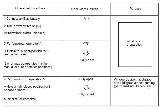
HINT:
- *1: Even if the door glass is in the fully open condition before performing step 3, perform the down operation for 1 second or more.
- *2: Do not stop the procedure during step 4.
(c) Procedure B
Reset the door glass position, and perform registration of the door glass position (fully closed, fully open) and sliding resistance learning.
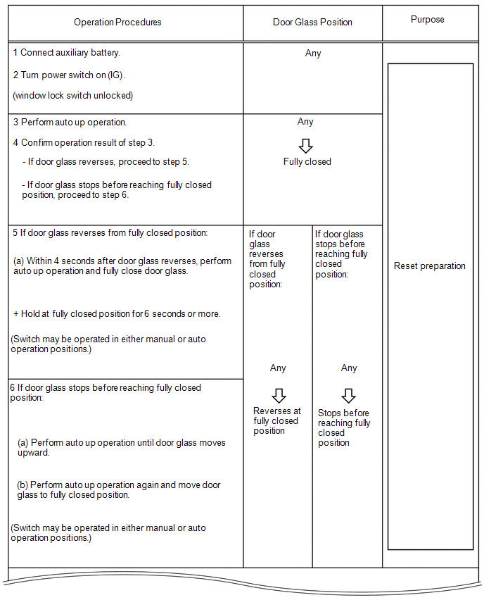
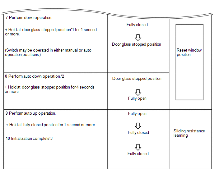
HINT:
- *1: The door glass stopped position is the fully open position stored in the ECU.
- *2: After performing step 7, return the switch to the neutral position once, and then perform an auto down operation.
- *3: After completion, check that the door glass can fully close via an auto up operation.
-
If the initialization is not completed properly, the LIN communication system may have a malfunction.
Click here
(d) Procedure C
Perform sliding resistance learning.
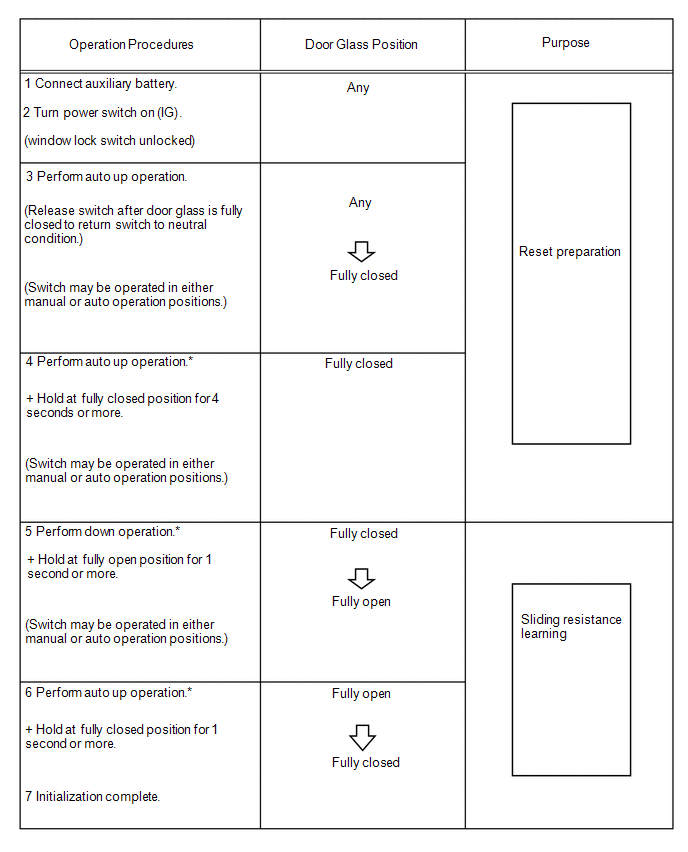
HINT:
- *: Do not stop the procedure during step 4, 5 or 6.
- If erroneous reverse operation of the door glass continues even after performing steps 4, 5 and 6, perform the procedure again from step 3.
READ NEXT:
 Problem Symptoms Table
PROBLEM SYMPTOMS TABLE NOTICE:
Recognition code registration is necessary when replacing the main body ECU (multiplex network body ECU).
If the main body ECU (multiplex network body ECU) is repla
Terminals Of Ecu
TERMINALS OF ECU CHECK MULTIPLEX NETWORK MASTER SWITCH ASSEMBLY (a) Disconnect the M10 multiplex network master switch assembly connector. (b) Measure the voltage and resistance according to the valu
Dtc Check / Clear
DTC CHECK / CLEAR CHECK DTC (a) Turn the power switch off. (b) Connect the Techstream to the DLC3. (c) Turn the power switch on (IG). (d) Turn the Techstream on. (e) Enter the following menus: Body El
SEE MORE:
Terminals Of Ecu
TERMINALS OF ECU CHECK INSTRUMENT PANEL JUNCTION BLOCK ASSEMBLY AND MAIN BODY ECU (MULTIPLEX NETWORK BODY ECU) (a) Remove the main body ECU (multiplex network body ECU). Click here *1 Main Body ECU (Multiplex Network Body ECU) - - (b) Measure the voltage and resistance according to t
Mass Air Flow Meter
ComponentsCOMPONENTS ILLUSTRATION *1 MASS AIR FLOW METER SUB-ASSEMBLY - - On-vehicle InspectionON-VEHICLE INSPECTION CAUTION / NOTICE / HINT NOTICE:
Perform the mass air flow meter sub-assembly inspection according to the procedures below.
Only replace the mass air flow meter sub
© 2016-2026 Copyright www.lexunx.com
