Lexus NX: Inspection
INSPECTION
PROCEDURE
1. INSPECT CHARCOAL CANISTER ASSEMBLY
| (a) Visually check the charcoal canister assembly for cracks or damage. If cracks or damage is found, replace the charcoal canister assembly. |
|
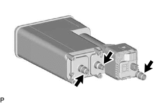
(b) Check the canister operation.
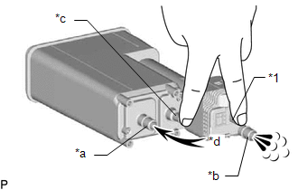
| *1 | Connector |
| *a | Vent Line Port |
| *b | Air Inlet Line Port |
| *c | Purge Line Port |
| *d | Air |
(1) With the purge line port and connector closed, blow air at 5 kPa (0.1 kgf/cm2, 0.7 psi) into the vent line port and check that air flows from the air inlet line port.
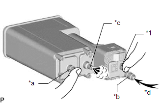
| (2) With the vent line port and connector closed, blow air at 5 kPa (0.1 kgf/cm2, 0.7 psi) into the air inlet line port and check that air flows from the purge line port. If the result is not as specified, replace the charcoal canister assembly. |
|
(c) Check for air leaks.
| (1) Connect a pressure gauge to the vent line port of the charcoal canister assembly. |
|
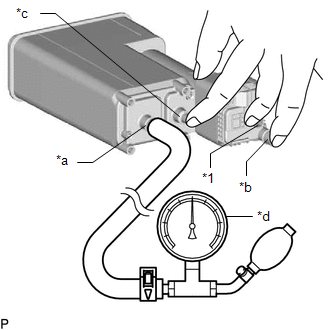
(2) With the purge line port, air inlet line port and connector closed, apply pressurized air at 19.6 kPa (0.2 kgf/cm2, 2.8 psi) into the vent line port, and then confirm that pressure is retained for 1 minute.
If the result is not as specified, replace the charcoal canister assembly.
READ NEXT:
 Installation
INSTALLATION PROCEDURE 1. INSTALL CANISTER PUMP MODULE (a) Engage the 2 claws to install a new canister pump module to the charcoal canister assembly. NOTICE:
Do not allow foreign matter such
Egr Cooler
ComponentsCOMPONENTS ILLUSTRATION *1 EGR COOLER ASSEMBLY *2 NO. 5 WATER BY-PASS HOSE *3 STUD BOLT *4 GASKET *5 NO. 1 WATER BY-PASS PIPE *6 NO. 1 EGR PIPE N*m (kgf
SEE MORE:
Throttle / Pedal Position Sensor "A" Minimum Stop Performance (P2109)
DESCRIPTION The idle speed is controlled by the Electronic Throttle Control System (ETCS). The ETCS is comprised of a throttle actuator, which operates the throttle valve, and a throttle position sensor, which detects the opening amount of the throttle valve. The ECM controls the throttle actuator t
Stereo Component Amplifier Disconnected (B15D3)
DESCRIPTION The radio receiver assembly and stereo component amplifier assembly are connected by the AVC-LAN communication line. This DTC is stored when an AVC-LAN communication error occurs between the radio receiver assembly and stereo component amplifier assembly. DTC No. Detection Item DT
