Lexus NX: Egr Cooler
Components
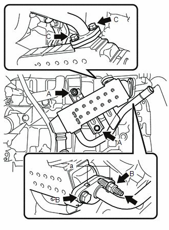
COMPONENTS
ILLUSTRATION
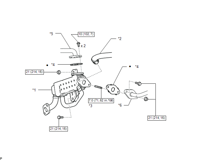
| *1 | EGR COOLER ASSEMBLY | *2 | NO. 5 WATER BY-PASS HOSE |
| *3 | STUD BOLT | *4 | GASKET |
| *5 | NO. 1 WATER BY-PASS PIPE | *6 | NO. 1 EGR PIPE |
.png) | N*m (kgf*cm, ft.*lbf): Specified torque | ● | Non-reusable part |
Removal
REMOVAL
PROCEDURE
1. REMOVE EXHAUST MANIFOLD CONVERTER SUB-ASSEMBLY
Click here .gif)
2. REMOVE EGR COOLER ASSEMBLY
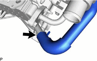
| (a) Slide the clamp and disconnect the No. 5 water by-pass hose from the EGR cooler assembly. |
|
| (b) Remove the nut and bolt, and disconnect the No. 1 EGR pipe from the EGR cooler assembly. |
|
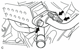
(c) Using an E8 "TORX" socket wrench, remove the stud bolt from the EGR cooler assembly.
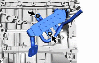
| (d) Remove the 2 bolts and disconnect the No. 1 water by-pass pipe from the EGR cooler assembly. |
|

| (e) Remove the nut, bolt and remove the EGR cooler assembly from the cylinder block sub-assembly. |
|
(f) Remove the 2 gaskets from the No. 1 EGR pipe and No. 1 water by-pass pipe.
Installation
INSTALLATION
PROCEDURE
1. INSTALL EGR COOLER ASSEMBLY
| (a) Install 2 new gaskets to the No. 1 EGR pipe and No. 1 water by-pass pipe. NOTICE: Make sure that the gasket is installed in the correct direction. |
|
(b) Temporarily install the EGR cooler assembly to the cylinder block sub-assembly with the nut A and bolt A.
HINT:
Nut A and bolt A can be installed to either side depending on the position of the stud bolt.
(c) Using an E8 "TORX" socket wrench, install the stud bolt to the EGR cooler assembly.
Torque:
7.0 N·m {71 kgf·cm, 62 in·lbf}
(d) Temporarily install the No. 1 EGR pipe to the EGR cooler assembly with nut B and bolt B.
(e) Temporarily install the No. 1 water by-pass pipe to the EGR cooler assembly with 2 bolts C.
(f) Tighten 2 bolts C.
Torque:
10 N·m {102 kgf·cm, 7 ft·lbf}
NOTICE:
Make sure that all installation surfaces of the EGR cooler assembly are evenly in contact when tightening the nuts and bolts.
(g) Tighten nut B and bolt B.
Torque:
21 N·m {214 kgf·cm, 15 ft·lbf}
(h) Tighten nut A and bolt A.
Torque:
21 N·m {214 kgf·cm, 15 ft·lbf}
(i) Connect the No. 5 water by-pass hose to the EGR cooler assembly, and slide the clamp to secure the hose.
2. INSTALL EXHAUST MANIFOLD CONVERTER SUB-ASSEMBLY
Click here .gif)
READ NEXT:
 Components
COMPONENTS ILLUSTRATION *1 AIR CLEANER CAP AND HOSE *2 EGR VALVE ASSEMBLY *3 NO. 1 ENGINE COVER SUB-ASSEMBLY *4 GASKET *5 NO. 1 EGR PIPE *6 NO. 1 WATER BY-PASS HOSE *
Removal
REMOVAL PROCEDURE 1. DRAIN ENGINE COOLANT Click here 2. REMOVE NO. 1 ENGINE COVER SUB-ASSEMBLY Click here 3. REMOVE AIR CLEANER CAP AND HOSE Click here 4. REMOVE EGR VALVE ASSEMBLY (a) Discon
SEE MORE:
Dtc Check / Clear
DTC CHECK / CLEAR CHECK DTC AND FREEZE FRAME DATA (a) Turn the power switch off. (b) Connect the Techstream to the DLC3. (c) Turn the power switch on (IG) and the Techstream on. (d) Enter the following menus: Chassis / Electric Parking Brake / Trouble Codes. (e) Check for DTC. Chassis > Electric
Data List / Active Test
DATA LIST / ACTIVE TEST DATA LIST HINT: Using the Techstream to read the Data List allows the values or states of switches, sensors, actuators and other items to be read without removing any parts. This non-intrusive inspection can be very useful because intermittent conditions or signals may be dis
