Lexus NX: Installation
INSTALLATION
PROCEDURE
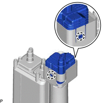
1. INSTALL CANISTER PUMP MODULE
| (a) Engage the 2 claws to install a new canister pump module to the charcoal canister assembly. NOTICE:
|
|
2. INSTALL CHARCOAL CANISTER ASSEMBLY
(a) Install the charcoal canister assembly with the 4 bolts and clip.
Torque:
20 N·m {204 kgf·cm, 15 ft·lbf}
| (b) Connect the vent line hose to the charcoal canister assembly. (1) Push the vent line hose into the vent line port and push the retainer to lock it. NOTICE:
|
|
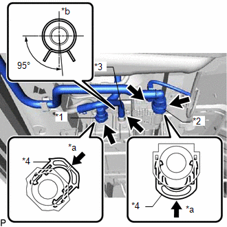
(c) Connect the air inlet line hose to the air inlet line port.
(1) Push the air inlet line hose into the air inlet line port and push the retainer to lock it.
NOTICE:
- Check for damage or foreign objects on the connected part.
- After connecting the air inlet line hose, check that the air inlet line hose and valve are securely connected by pulling on them.
(d) Connect the purge line hose to the charcoal canister assembly, and slide the clamp to secure the hose.
HINT:
Make sure the hose clamp is oriented as shown in the illustration.
(e) Connect the connector to the canister pump module.
3. INSTALL FRONT FLOOR COVER CENTER LH
Click here .gif)
READ NEXT:
 Egr Cooler
ComponentsCOMPONENTS ILLUSTRATION *1 EGR COOLER ASSEMBLY *2 NO. 5 WATER BY-PASS HOSE *3 STUD BOLT *4 GASKET *5 NO. 1 WATER BY-PASS PIPE *6 NO. 1 EGR PIPE N*m (kgf
Components
COMPONENTS ILLUSTRATION *1 AIR CLEANER CAP AND HOSE *2 EGR VALVE ASSEMBLY *3 NO. 1 ENGINE COVER SUB-ASSEMBLY *4 GASKET *5 NO. 1 EGR PIPE *6 NO. 1 WATER BY-PASS HOSE *
SEE MORE:
Lost Communication with Main Body ECU (U0142,U0208)
DESCRIPTION The multiplex tilt and telescopic ECU receives signals from the main body ECU (multiplex network body ECU) and front power seat switch via CAN communication. DTC No. Detection Item DTC Detection Condition Trouble Area U0142 Lost Communication with Main Body ECU Lost comm
Installation
INSTALLATION CAUTION / NOTICE / HINT HINT:
Use the same procedure for the RH and LH sides.
The procedure described below is for the LH side.
PROCEDURE 1. INSTALL REAR LIGHT ASSEMBLY LH (a) Attach the guide, clip and pin to set the rear light assembly LH. *a Pin *b Gui
