Lexus NX: Installation
INSTALLATION
CAUTION / NOTICE / HINT
HINT:
Perform "Inspection After Repairs" after replacing the fuel pump.
Click here .gif)
PROCEDURE
1. INSTALL FUEL SUCTION TUBE ASSEMBLY
(a) Install a new gasket onto the fuel suction tube assembly.
| (b) With the paint mark facing the top of the vehicle, connect the fuel hose to the fuel suction tube assembly and secure the hose with the clamp. |
|
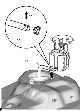
(c) Install the fuel suction tube assembly to the fuel tank assembly.
NOTICE:
Be careful not to damage the fuel suction tube assembly.
2. INSTALL FUEL TANK VENT TUBE SET PLATE
(a) Install the fuel tank vent tube set plate with the 8 bolts.
Torque:
6.0 N·m {61 kgf·cm, 53 in·lbf}
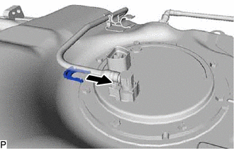
3. CONNECT FUEL TANK MAIN TUBE SUB-ASSEMBLY
(a) Connect the fuel tank main tube sub-assembly to the fuel suction plate sub-assembly, then install the tube joint clip.
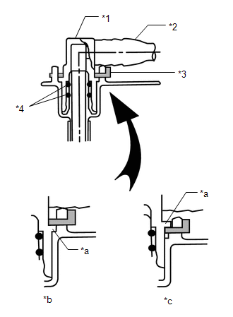
| *1 | Fuel Tube Joint |
| *2 | Fuel Tank Main Tube Sub-assembly |
| *3 | Tube Joint Clip |
| *4 | O-Ring |
| *a | Collar |
| *b | CORRECT |
| *c | INCORRECT |
- Check that there are no scratches or foreign objects on the connecting parts.
- Check that the fuel tube joint is inserted securely.
- Make sure that the fuel joint clip is above the flange of the fuel tank main tube sub-assembly.
- After installing the tube joint clip, make sure that the fuel tank main tube sub-assembly cannot be pulled out.
- Be careful not to damage the tube joint clip. If the tube joint clip is damaged, replace it.
4. INSTALL FUEL TANK ASSEMBLY
Click here
READ NEXT:
 Fuel Pump Ecu
ComponentsCOMPONENTS ILLUSTRATION *1 FUEL PUMP CONTROL ECU ASSEMBLY *2 PARKING BRAKE ECU ASSEMBLY N*m (kgf*cm, ft.*lbf): Specified torque - - RemovalREMOVAL PROCEDURE 1. REMO
Fuel Sender Gauge Assembly
ComponentsCOMPONENTS ILLUSTRATION *1 FUEL SENDER GAUGE ASSEMBLY - - N*m (kgf*cm, ft.*lbf): Specified torque - - RemovalREMOVAL PROCEDURE 1. REMOVE FUEL TANK ASSEMBLY Click he
SEE MORE:
Parts Location
PARTS LOCATION ILLUSTRATION *A for 2WD *B for AWD *1 AIR CONDITIONING TUBE AND ACCESSORY ASSEMBLY (AIR CONDITIONER PRESSURE SENSOR) *2 THERMISTOR ASSEMBLY (AMBIENT TEMPERATURE SENSOR) *3 HEATER ACCESSORY ASSEMBLY *4 PTC HTR NO.1 RELAY *5 PTC HTR NO.2 RELAY *6
ABS Warning Light does not Come ON
DESCRIPTION The skid control ECU (brake booster with master cylinder assembly) is connected to the combination meter assembly via CAN communication. CAUTION / NOTICE / HINT NOTICE: When replacing the skid control ECU (brake booster with master cylinder assembly), perform initialization and calibrati
