Lexus NX: Reassembly
REASSEMBLY
CAUTION / NOTICE / HINT
NOTICE:
Do not try to remove the black nylon tube as it is welded to the fuel suction tube assembly.
Click here .gif)
HINT:
Perform "Inspection After Repairs" after replacing the fuel pump.
Click here
PROCEDURE
1. INSTALL FUEL PUMP ASSEMBLY WITH FILTER
HINT:
Perform "Inspection After Repairs" after replacing the fuel pump.
Click here
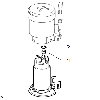
| (a) Apply gasoline to a new O-ring. Then install the fuel pump spacer and O-ring to the fuel pump assembly with filter. |
|
(b) Connect the fuel pump harness connector.
(c) Attach the 5 claws of the fuel filter assembly and install the fuel pump assembly with filter.
2. INSTALL NO. 1 FUEL SUCTION SUPPORT
(a) Attach the 2 claws and install the No. 1 fuel suction support to the fuel filter assembly.
3. INSTALL NO. 1 FUEL SUB-TANK
(a) Apply gasoline to a new O-ring and install it to the jet pump.
| (b) Install the jet pump while aligning it to the installation position of the No. 1 fuel sub-tank. |
|
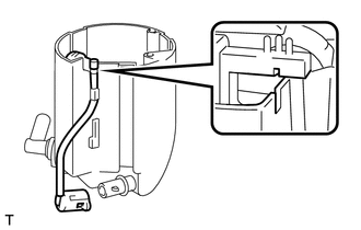
(c) Attach the claw to install the jet pump nozzle.
(d) Push the 2 claws into the holes and install the No. 1 fuel sub-tank to the fuel filter assembly.
| (e) Connect the fuel pump harness connector. |
|
.png)
(f) Install the No. 2 fuel tank cushion and No. 3 fuel tank cushion to the fuel suction plate sub-assembly, then install them to the No. 1 fuel sub-tank.
(g) Install a new fuel tank pipe setting holder.
HINT:
Slightly lower the fuel suction plate sub-assembly to install the fuel tank pipe setting holder.
READ NEXT:
 Installation
INSTALLATION CAUTION / NOTICE / HINT HINT: Perform "Inspection After Repairs" after replacing the fuel pump. Click here PROCEDURE 1. INSTALL FUEL SUCTION TUBE ASSEMBLY (a) Install a new gasket onto
Fuel Pump Ecu
ComponentsCOMPONENTS ILLUSTRATION *1 FUEL PUMP CONTROL ECU ASSEMBLY *2 PARKING BRAKE ECU ASSEMBLY N*m (kgf*cm, ft.*lbf): Specified torque - - RemovalREMOVAL PROCEDURE 1. REMO
Fuel Sender Gauge Assembly
ComponentsCOMPONENTS ILLUSTRATION *1 FUEL SENDER GAUGE ASSEMBLY - - N*m (kgf*cm, ft.*lbf): Specified torque - - RemovalREMOVAL PROCEDURE 1. REMOVE FUEL TANK ASSEMBLY Click he
SEE MORE:
Components
COMPONENTS ILLUSTRATION *1 DECK TRIM SIDE PANEL ASSEMBLY LH *2 FUEL FILLER OPENING LID LOCK RETAINER *3 FUEL LID WITH MOTOR LOCK ASSEMBLY *4 LUGGAGE HOLD BELT STRIKER ASSEMBLY *5 NO. 1 LUGGAGE COMPARTMENT TRIM HOOK *6 REAR DOOR OPENING TRIM WEATHERSTRIP LH *7 REAR
Dtc Check / Clear
DTC CHECK / CLEAR CHECK DTC (a) Connect the Techstream to the DLC3. (b) Turn the power switch on (IG). (c) Turn the Techstream on. (d) Enter the following menus: Body Electrical / Main Body / Trouble Codes. Body Electrical > Main Body > Trouble Codes (e) Check the details of the DTCs. Click he
