Lexus NX: Inspection
INSPECTION
PROCEDURE
1. INSPECT CRUISE CONTROL MAIN SWITCH
(a) w/o Dynamic Radar Cruise Control System:
(1) Measure the resistance according to the value(s) in the table below.
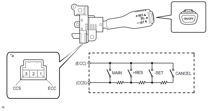
| *a | Component without harness connected (Cruise Control Main Switch) | - | - |
Standard Resistance:
| Tester Connection | Condition | Specified Condition |
|---|---|---|
| 1 (ECC) - 3 (CCS) | Cruise control main switch (ON-OFF button) released | 1 MΩ or higher |
| Cruise control main switch (ON-OFF button) pushed | Below 2.5 Ω | |
| +RES switch ON | 236 to 244 Ω | |
| -SET switch ON | 618 to 642 Ω | |
| CANCEL switch ON | 1510 to 1570 Ω |
If the result is not as specified, replace the cruise control main switch.
(b) w/ Dynamic Radar Cruise Control System:
(1) Measure the resistance according to the value(s) in the table below.
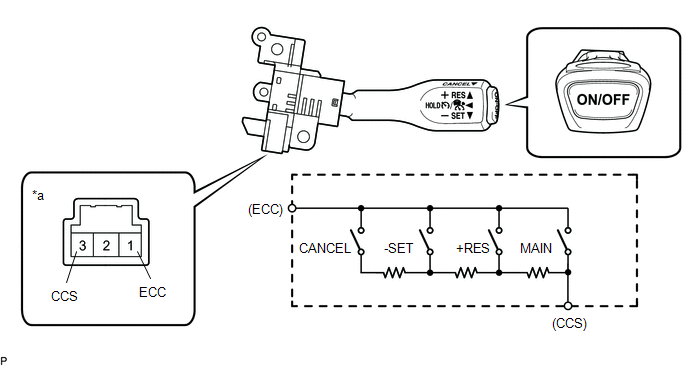
| *a | Component without harness connected (Cruise Control Main Switch) | - | - |
Standard Resistance:
| Tester Connection | Condition | Specified Condition |
|---|---|---|
| 1 (ECC) - 3 (CCS) | Cruise control main switch (ON-OFF button) released | 1 MΩ or higher |
| Cruise control main switch (ON-OFF button) pushed | Below 2.5 Ω | |
| +RES switch ON | 236 to 244 Ω | |
| -SET switch ON | 618 to 642 Ω | |
| CANCEL switch ON | 1510 to 1570 Ω |
If the result is not as specified, replace the cruise control main switch.
READ NEXT:
 Installation
INSTALLATION PROCEDURE 1. INSTALL CRUISE CONTROL MAIN SWITCH (a) Pass the wire harness under the rib as shown in the illustration. *1 Wire Harness *a Rib *b Guide Connector
Precaution
PRECAUTION HANDLING PRECAUTION FOR DYNAMIC RADAR CRUISE CONTROL SYSTEM Keep in mind the following points when servicing vehicles equipped with the dynamic radar cruise control system. (a) The dynamic
SEE MORE:
Vehicle Speed Signal (C1541)
DESCRIPTION The power steering ECU assembly receives vehicle speed signals from the skid control ECU (brake booster with master cylinder assembly) via CAN communication. The ECU provides appropriate assisting force in accordance with the vehicle speed based on the signals. DTC No. Detection Ite
Side doors
The vehicle can be locked and
unlocked using the entry function,
wireless remote control or door
lock switch.
Unlocking and locking the doors
from the outside
■ Using the smart access system with
push-button start
Carry the electronic key to enable this
function.
Grip the driver's d
