Lexus NX: Inspection
INSPECTION
PROCEDURE
1. INSPECT VEHICLE SOUND SWITCH
| (a) Check the vehicle sound switch on/off operation (1) Measure the resistance according to the value(s) in the table below. Standard Resistance:
If the result is not as specified, replace the vehicle sound switch. |
|
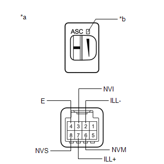
(b) Inspect the switch indicator
(1) Apply auxiliary battery voltage to the vehicle sound switch connector and check that the switch indicator comes on.
OK:
| Measurement Condition | Condition | Specified Condition |
|---|---|---|
| Auxiliary battery positive (+) → 8 (NVS) Auxiliary battery negative (-) → 4 (E) | Vehicle sound switch on | Switch indicator comes on |
If the result is not as specified, replace the vehicle sound switch.
(c) Check the volume control function
(1) Measure the resistance according to the value(s) in the table below.
Standard Resistance:
| Tester Connection | Condition | Specified Condition |
|---|---|---|
| 6 (NVM) - 8 (NVS) | Vehicle sound switch volume set to maximum | 4.08 to 2.72 kΩ |
| Vehicle sound switch volume set to minimum | 0.42 to 0.28 kΩ |
If the result is not as specified, replace the vehicle sound switch.
(d) Inspect the switch illumination
(1) Apply auxiliary battery voltage to the vehicle sound switch connector and check that the switch illumination comes on.
OK:
| Measurement Condition | Specified Condition |
|---|---|
| Auxiliary battery positive (+) → 7 (ILL+) Auxiliary battery negative (-) → 2 (ILL-) | Switch illumination comes on |
If the result is not as specified, replace the vehicle sound switch.
READ NEXT:
 Installation
INSTALLATION PROCEDURE 1. INSTALL VEHICLE SOUND SWITCH (a) Attach the 2 claws to install the vehicle sound switch. 2. INSTALL LOWER NO. 1 INSTRUMENT PANEL FINISH PANEL Click here 3. INSTALL NO. 1
Parts Location
PARTS LOCATION ILLUSTRATION *1 VEHICLE SOUND SWITCH *2 STEREO COMPONENT EQUALIZER ASSEMBLY *3 NO. 1 SPEAKER ASSEMBLY WITH BOX *4 HYBRID VEHICLE CONTROL ECU *5 MAIN BODY ECU (
SEE MORE:
System Description
SYSTEM DESCRIPTION ADAPTIVE VARIABLE SUSPENSION SYSTEM DESCRIPTION (a) The absorber control ECU receives signals from the sensors and switches to control the absorber control actuator (shock absorber assembly). It uses these signals to optimally control the damping force in accordance with the drivi
Reassembly
REASSEMBLY PROCEDURE 1. INSTALL NUT (a) Install the 2 nuts. 2. INSTALL RADIATOR GRILLE EMBLEM (a) Attach the claw and guide to install the radiator grille emblem. (b) Install the 2 screws. 3. INSTALL RADIATOR GRILLE 4. INSTALL RADIATOR GRILLE MOULDING (a) Attach the 12
