Lexus NX: Removal
REMOVAL
PROCEDURE
1. REMOVE CONSOLE ARMREST ASSEMBLY
Click here .gif)
2. REMOVE UPPER NO. 2 CONSOLE PANEL GARNISH
Click here
3. REMOVE INSTRUMENT SIDE PANEL LH
Click here
4. REMOVE NO. 1 INSTRUMENT PANEL SAFETY PAD SUB-ASSEMBLY
Click here
5. REMOVE NO. 1 INSTRUMENT PANEL UNDER COVER SUB-ASSEMBLY
Click here
6. REMOVE LOWER NO. 1 INSTRUMENT PANEL FINISH PANEL
Click here
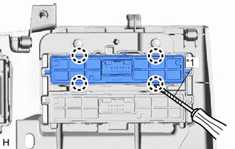
7. REMOVE COMBINATION SWITCH ASSEMBLY (for Upper Side)
| (a) Using a screwdriver, detach the 4 claws and remove the combination switch assembly. HINT: Tape the screwdriver tip before use. |
|
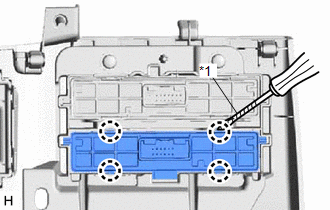
8. REMOVE NO. 2 COMBINATION SWITCH ASSEMBLY (for Lower Side)
| (a) Using a screwdriver, detach the 4 claws and remove the No. 2 combination switch assembly. HINT: Tape the screwdriver tip before use. |
|
READ NEXT:
 Installation
INSTALLATION PROCEDURE 1. INSTALL COMBINATION SWITCH ASSEMBLY (for Upper Side) (a) Attach the 4 claws to install the combination switch assembly. 2. INSTALL NO. 2 COMBINATION SWITCH ASS
Components
COMPONENTS ILLUSTRATION *A for 8 Inch Display *B for 10.3 Inch Display *1 CENTER INSTRUMENT CLUSTER FINISH PANEL ASSEMBLY *2 CONSOLE ARMREST ASSEMBLY *3 INSTRUMENT PANEL FINI
SEE MORE:
Washer Fluid Level Warning Switch Circuit
DESCRIPTION When the volume of washer fluid decreases to below a certain level (when the level warning switch assembly is turned on), the multi-information display warns the driver by displaying a message. WIRING DIAGRAM CAUTION / NOTICE / HINT NOTICE: When replacing the combination meter assembly,
Removal
REMOVAL CAUTION / NOTICE / HINT NOTICE: When replacing the windshield glass of a vehicle equipped with a forward recognition camera, make sure to use a Lexus genuine part. If a non-Lexus genuine part is used, the forward recognition camera may not be able to be installed due to a missing bracket. Al
