Lexus NX: Inspection
INSPECTION
PROCEDURE
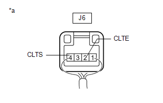
1. INSPECT AUTOMATIC LIGHT CONTROL SENSOR
| (a) Disconnect the automatic light control sensor connector. |
|
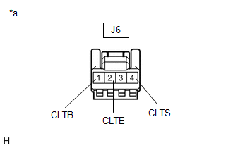
(b) Measure the voltage and resistance according to the value(s) in the table below.
Standard Voltage:
| Tester Connection | Condition | Specified Condition |
|---|---|---|
| J6-1 (CLTB) - J6-2 (CLTE) | Power switch off | Below 1 V |
| Power switch on (IG) | 11 to 14 V |
Standard Resistance:
| Tester Connection | Condition | Specified Condition |
|---|---|---|
| J6-2 (CLTE) - Body ground | Always | Below 1 Ω |
If the result is not as specified, there may be a malfunction on the wire harness side.
| (c) Reconnect the automatic light control sensor connector. |
|
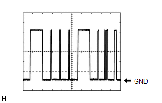
(d) Connect an oscilloscope to the automatic light control sensor connector.
| (e) Check the waveform. OK:
HINT: The communication waveform changes according to the surrounding brightness. If the result is not as specified, the automatic light control sensor may be malfunctioning. |
|
READ NEXT:
 Installation
INSTALLATION PROCEDURE 1. INSTALL AUTOMATIC LIGHT CONTROL SENSOR (a) Attach the 2 claws to install the automatic light control sensor. 2. INSTALL NO. 1 SPEAKER OPENING COVER ASSEMBLY Click here 3.
Components
COMPONENTS ILLUSTRATION *1 CLEARANCE LIGHT ASSEMBLY LH *2 FRONT BUMPER ASSEMBLY *3 FRONT TURN SIGNAL LIGHT BULB - -
SEE MORE:
Lost Communication with Haptic Device (B1323-B1326)
DESCRIPTION These DTCs are stored when communication between the radio receiver assembly and remote operation controller assembly (remote touch), combination meter assembly, combination meter mirror ECU* or clock assembly is not possible.
*: w/ Headup Display
DTC No. Detection Item DTC
Installation
INSTALLATION CAUTION / NOTICE / HINT HINT:
Use the same procedure for the RH and LH sides.
The procedure listed below is for the LH side.
PROCEDURE 1. INSTALL SIDE MUDGUARD SUB-ASSEMBLY LH HINT: When installing the side mudguard sub-assembly LH, heat the vehicle body and side mudguard sub-as
