Lexus NX: Components
COMPONENTS
ILLUSTRATION
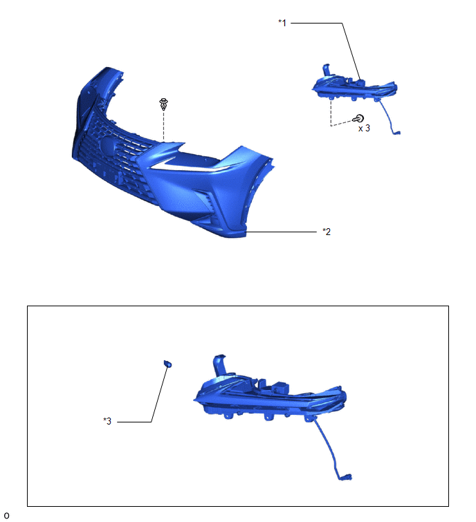
| *1 | CLEARANCE LIGHT ASSEMBLY LH | *2 | FRONT BUMPER ASSEMBLY |
| *3 | FRONT TURN SIGNAL LIGHT BULB | - | - |
READ NEXT:
 Removal
REMOVAL CAUTION / NOTICE / HINT HINT:
Use the same procedure for the RH and LH sides.
The procedure described below is for the LH side.
PROCEDURE 1. REMOVE FRONT BUMPER ASSEMBLY Click here 2
Disassembly
DISASSEMBLY CAUTION / NOTICE / HINT HINT:
Use the same procedure for the RH and LH sides.
The procedure listed below is for the LH side.
PROCEDURE 1. REMOVE FRONT TURN SIGNAL LIGHT BULB (a) Tu
Inspection
INSPECTION PROCEDURE 1. INSPECT CLEARANCE LIGHT ASSEMBLY LH (a) Apply battery voltage to the connector and check the light illumination condition. OK: Condition Specified Condition Batter
SEE MORE:
Navigation Processor Malfunction (B15AD)
DESCRIPTION These DTCs are stored when a malfunction occurs in the navigation ECU. DTC No. Detection Item DTC Detection Condition Trouble Area B15AD Navigation Processor Malfunction When either of the conditions below is met:
A short to ground, short to +B or open occurs in the g
Data List / Active Test
DATA LIST / ACTIVE TEST DATA LIST HINT: Using the Techstream to read the Data List allows the values or states of switches, sensors, actuators and other items to be read without removing any parts. This non-intrusive inspection can be very useful because intermittent conditions or signals may be dis
© 2016-2026 Copyright www.lexunx.com
