Lexus NX: Inspection
INSPECTION
PROCEDURE
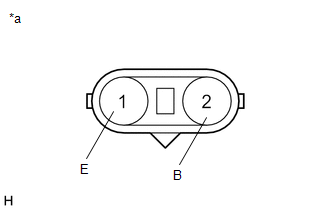
1. INSPECT FOG LIGHT ASSEMBLY LH
| (a) Apply battery voltage to the connector and check the light illumination condition. OK:
If the result is not as specified, replace the fog light assembly LH. |
|
2. INSPECT FOG LIGHT ASSEMBLY RH
| (a) Apply battery voltage to the connector and check the light illumination condition. OK:
If the result is not as specified, replace the fog light assembly RH. |
|
READ NEXT:
 Adjustment
ADJUSTMENT CAUTION / NOTICE / HINT HINT:
Use the same procedure for the RH and LH sides.
The procedure listed below is for the LH side.
It is possible that a fog light assembly is incorrectly i
Installation
INSTALLATION CAUTION / NOTICE / HINT HINT:
Use the same procedure for the RH and LH sides.
The procedure described below is for the LH side.
PROCEDURE 1. INSTALL FOG LIGHT ASSEMBLY LH (a) Atta
SEE MORE:
Removal
REMOVAL PROCEDURE 1. PRECAUTION NOTICE: After turning the power switch is turned off, there may be a waiting time before disconnecting the auxiliary negative (-) battery terminal. Click here 2. CUSTOMIZE POWER TILT AND POWER TELESCOPIC STEERING COLUMN SYSTEM (a) Disable the auto tilt away function
Voice Guidance Circuit between Radio Receiver and Stereo Component Amplifier
DESCRIPTION This circuit is used when the voice switch of the steering pad switch assembly is pushed. Using this circuit, the radio and display receiver assembly sends signals to the stereo component amplifier assembly. WIRING DIAGRAM PROCEDURE 1. CHECK HARNESS AND CONNECTOR (RADIO RECEIVER A
© 2016-2026 Copyright www.lexunx.com
