Lexus NX: Inspection
INSPECTION
PROCEDURE
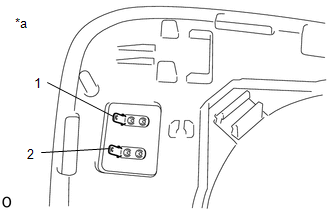
1. INSPECT OUTER MIRROR LH
| (a) Check the outer mirror heater operation. (1) Measure the resistance according to the value(s) in the table below. Standard Resistance:
If the result is not as specified, replace the outer mirror LH. |
|
(b) w/ EC Mirror:
Check EC mirror operation.
(1) Connect a new 1.5 V dry-cell battery.
| (2) Apply 1.5 V dry-cell battery voltage to the terminals of the connector, and check that the EC mirror operation. NOTICE: Do not apply a voltage of higher than 1.5 V. OK:
If the result is not as specified, replace the outer mirror LH. |
|
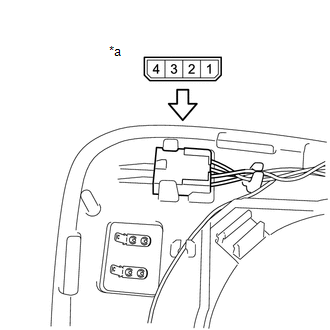
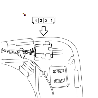
(c) w/ Blind Spot Monitor System:
Check the operation of the blind spot monitor indicator.
| (1) Connect 4 new 1.5 V dry-cell batteries in series. |
|
(2) Apply 6 V dry-cell batteries to the terminals of the connector, and check the blind spot monitor indicator condition.
OK:
| Tester Connection | Specified Condition |
|---|---|
| Positive (+) end of the 6 V dry-cell battery → 3 Negative (-) end of the 6 V dry-cell battery → 2 | Blind spot monitor indicator comes on |
If the result is not as specified, replace the outer mirror LH.
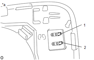
2. INSPECT OUTER MIRROR RH
| (a) Check the outer mirror heater operation. (1) Measure the resistance according to the value(s) in the table below. Standard Resistance:
If the result is not as specified, replace the outer mirror RH. |
|
(b) w/ EC Mirror:
Check EC mirror operation.
(1) Connect a new 1.5 V dry-cell battery.
| (2) Apply 1.5 V dry-cell battery voltage to the terminals of the connector, and check that the EC mirror operation. NOTICE: Do not apply a voltage of higher than 1.5 V. OK:
If the result is not as specified, replace the outer mirror RH. |
|

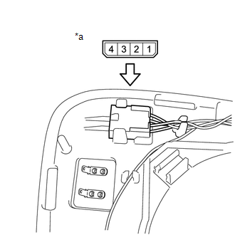
(c) w/ blind spot monitor system
Check the operation of the blind spot monitor indicator.
| (1) Connect 4 new 1.5 V dry-cell batteries in series. |
|
(2) Apply 6 V dry-cell batteries to the terminals of the connector, and check the blind spot monitor indicator condition.
OK:
| Tester Connection | Specified Condition |
|---|---|
| Positive (+) end of the 6 V dry-cell battery → 3 Negative (-) end of the 6 V dry-cell battery → 2 | Blind spot monitor indicator comes on |
If the result is not as specified, replace the outer mirror RH.
READ NEXT:
 Installation
INSTALLATION CAUTION / NOTICE / HINT HINT:
Use the same procedure for the RH and LH sides.
The procedure listed below is for the LH side.
PROCEDURE 1. INSTALL OUTER MIRROR LH (a) w/o EC Mir
Parts Location
PARTS LOCATION ILLUSTRATION *1 INNER REAR VIEW MIRROR ASSEMBLY *2 OUTER REAR VIEW MIRROR ASSEMBLY LH *3 OUTER REAR VIEW MIRROR ASSEMBLY RH *4 OUTER MIRROR LH *5 OUTER MIRROR
SEE MORE:
Evaporative Emission Pressure Switching Valve Stuck OFF (P2420)
DTC SUMMARY DTC No. Detection Item DTC Detection Condition Trouble Area MIL Memory P2420 Evaporative Emission Pressure Switching Valve Stuck OFF Following condition met during key-off EVAP monitor: EVAP pressure change when vent valve closed (on) less than 0.3 kPa(gauge) [2.25 m
Front Occupant Classification Sensor LH Collision Detection (B1785)
DESCRIPTION DTC B1785 is stored when the occupant detection ECU receives a collision detection signal, which is sent by the front occupant classification sensor LH when an accident occurs. DTC B1785 is also stored when the front seat adjuster assembly RH is subjected to a strong impact, even if an a
