Lexus NX: Parts Location
Lexus NX Service Manual / Vehicle Interior / Meter / Gauge / Display / Headup Display System / Parts Location
PARTS LOCATION
ILLUSTRATION
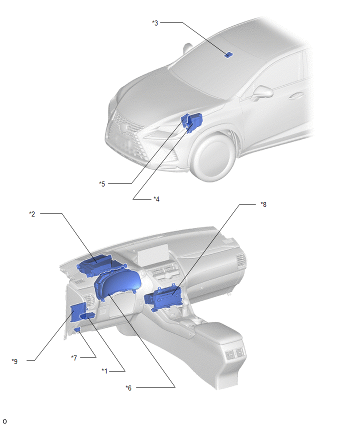
| *1 | HEADUP DISPLAY SWITCH ASSEMBLY | *2 | METER MIRROR SUB-ASSEMBLY |
| *3 | FORWARD RECOGNITION CAMERA | *4 | NO. 2 ENGINE ROOM RELAY BLOCK - ECU-B NO.1 FUSE |
| *5 | ECM | *6 | COMBINATION METER ASSEMBLY |
| *7 | DLC3 | *8 | RADIO RECEIVER ASSEMBLY |
| *9 | MAIN BODY ECU(MULTIPLEX NETWORK BODY ECU) | - | - |
READ NEXT:
 System Diagram
SYSTEM DIAGRAM
System Description
SYSTEM DESCRIPTION HEADUP DISPLAY SYSTEM DESCRIPTION HINT:
The meter mirror sub-assembly receives signals from the combination meter assembly via the CAN communication line. Information is displaye
Customize Parameters
CUSTOMIZE PARAMETERS CUSTOMIZE HEADUP DISPLAY SYSTEM (a) Customizing with the Techstream (1) Connect the Techstream to the DLC3. (2) Turn the power switch on (IG). (3) Turn the Techstream on. (4) Ente
SEE MORE:
Illumination Circuit
DESCRIPTION Power is supplied to the radio receiver assembly and steering pad switch assembly when the light control switch is in the tail or head position. WIRING DIAGRAM CAUTION / NOTICE / HINT NOTICE: The vehicle is equipped with a Supplemental Restraint System (SRS) which includes components su
Drive Start Control System
DESCRIPTION The drive start control is controlled by the hybrid vehicle control ECU. If the hybrid vehicle control ECU determines that the shift lever and accelerator pedal are operated abnormally, driving torque is restricted and, when necessary, a warning is displayed on the combination meter asse
© 2016-2026 Copyright www.lexunx.com
