Lexus NX: Inspection
INSPECTION
PROCEDURE
1. INSPECT FRONT SEAT ADJUSTER ASSEMBLY LH (w/o Memory)
(a) Check the operation of the slide motor.
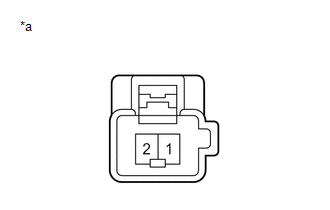
| (1) Apply auxiliary battery voltage to the slide motor connector, and check that the front seat adjuster assembly LH operates smoothly as follows. OK:
If the result is not as specified, replace the front seat adjuster assembly LH. |
|
| (b) Check the operation of the front vertical motor. (1) Apply auxiliary battery voltage to the front vertical motor connector, and check that the front seat adjuster assembly LH operates smoothly as follows. OK:
If the result is not as specified, replace the front seat adjuster assembly LH. |
|
| (c) Check the operation of the rear lifter motor. (1) Apply auxiliary battery voltage to the rear lifter motor connector, and check that the front seat adjuster assembly LH operates smoothly as follows. OK:
If the result is not as specified, replace the front seat adjuster assembly LH. |
|
2. INSPECT SEPARATE TYPE FRONT SEATBACK SPRING ASSEMBLY LH (w/o Memory)
(a) Check the operation of the reclining motor.
| (1) Apply auxiliary battery voltage to the reclining motor connector, and check that the separate type front seatback spring assembly LH operates smoothly as follows. OK:
If the result is not as specified, replace the separate type front seatback spring assembly LH. |
|
3. INSPECT FRONT SEAT ADJUSTER ASSEMBLY RH (w/o Memory)
(a) Check the operation of the slide motor.
| (1) Apply auxiliary battery voltage to the slide motor connector, and check that the front seat adjuster assembly RH operates smoothly as follows. OK:
If the result is not as specified, replace the front seat adjuster assembly RH. |
|
| (b) Check the operation of the front vertical motor. (1) Apply auxiliary battery voltage to the front vertical motor connector, and check that the front seat adjuster assembly RH operates smoothly as follows. OK:
If the result is not as specified, replace the front seat adjuster assembly RH. |
|
| (c) Check the operation of the rear lifter motor. (1) Apply auxiliary battery voltage to the rear lifter motor connector, and check that the front seat adjuster assembly RH operates smoothly as follows. OK:
If the result is not as specified, replace the front seat adjuster assembly RH. |
|
4. INSPECT SEPARATE TYPE FRONT SEATBACK SPRING ASSEMBLY RH (w/o Memory)
(a) Check the operation of the reclining motor.
| (1) Apply auxiliary battery voltage to the reclining motor connector, and check that the separate type front seatback spring assembly RH operates smoothly as follows. OK:
If the result is not as specified, replace the separate type front seatback spring assembly RH. |
|
READ NEXT:
 Reassembly
REASSEMBLY CAUTION / NOTICE / HINT CAUTION: Wear protective gloves. Sharp areas on the parts may injure your hands. HINT:
Use the same procedure for the RH and LH sides.
The procedure listed belo
Installation
INSTALLATION CAUTION / NOTICE / HINT CAUTION: Wear protective gloves. Sharp areas on the parts may injure your hands. HINT:
Use the same procedure for the RH and LH sides.
The procedure listed be
SEE MORE:
Problem Symptoms Table
PROBLEM SYMPTOMS TABLE HINT:
Use the table below to help determine the cause of problem symptoms. If multiple suspected areas are listed, the potential causes of the symptoms are listed in order of probability in the "Suspected Area" column of the table. Check each symptom by checking the suspect
System Diagram
SYSTEM DIAGRAM Sender Receiver Signal Line
*: w/ Blind Spot Monitor System
Parking Assist ECU Multi-display Assembly Display GVIF cable Radio Receiver Assembly Multi-display Assembly Display GVIF cable Steering Sensor Parking Assist ECU
Data continuity
