Lexus NX: Inspection
INSPECTION
PROCEDURE
1. INSPECT SPIRAL WITH SENSOR CABLE SUB-ASSEMBLY
NOTICE:
- Do not remove the steering sensor from the spiral with sensor cable sub-assembly.
- As the spiral with sensor cable sub-assembly may break, do not rotate the spiral with sensor cable sub-assembly more than the specified amount.
(a) Visually check for defects with the spiral with sensor cable sub-assembly.
(1) The defects are as follows:
- Scratches
- Small cracks
- Dents
- Chips
- Cracks or other damage to the connector
OK:
No defects are found.
If any of the defects is found, replace the spiral with sensor cable sub-assembly with a new one.
(b) Check the spiral with sensor cable sub-assembly.
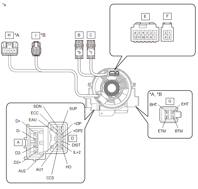
| *A | w/ Steering Heater, w/ Steering Vibration | *B | w/ Steering Heater, w/o Steering Vibration |
| *a | Component without harness connected (Spiral Cable sub-assembly) | *b | Color: Light Green |
| *c | Color: Black | - | - |
 | Interlock | - | - |
NOTICE:
When rotating the spiral with sensor cable sub-assembly, make sure to push on the interlock indicated in the illustration to release the interlock mechanism.
(1) Set the spiral with sensor cable sub-assembly to the center position.
Click here .gif)
(2) Measure the resistance between each terminal of the spiral with sensor cable sub-assembly according to the table below.
Standard Resistance:
| Tester Connection | Condition | Specified Condition |
|---|---|---|
|
*A: w/ Steering Heater, w/o Steering Vibration
*B: w/ Steering Heater, w/ Steering Vibration | ||
| A-1 (D+) - B-2 | Always | Below 1 Ω |
| A-2 (D-) - B-1 | Always | Below 1 Ω |
| A-3 (D2-) - C-1 | Always | Below 1 Ω |
| A-4 (D2+) - C-2 | Always | Below 1 Ω |
| D-1 (SDN) - F-3 | Always | 3 Ω or less |
| D-2 (ECC) - F-4 | Always | 3 Ω or less |
| D-3 (EAU) - E-8 | Always | 3 Ω or less |
| D-5 (AU2) - E-10 | Always | 3 Ω or less |
| D-6 (AU1) - E-11 | Always | 3 Ω or less |
| D-7 (CCS) - E-12 | Always | 3 Ω or less |
| D-8 (SUP) - F-1 | Always | 3 Ω or less |
| D-10 (+DP) - E-2 | Always | 3 Ω or less |
| D-11 (+DP2) - E-3 | Always | 3 Ω or less |
| D-12 (DIST) - E-4 | Always | 3 Ω or less |
| D-13 (IL+2) - E-5 | Always | 3 Ω or less |
| D-14 (HO) - E-6 | Always | 3 Ω or less |
| G-1 (BTM) - I-1*A | Always | Below 0.1 Ω |
| G-2 (EHT) - I-3*A | Always | Below 0.1 Ω |
| G-3 (ETM) - I-2*A | Always | Below 0.1 Ω |
| G-4 (BHT) - I-4*A | Always | Below 0.1 Ω |
| G-1 (BTM) - H-2*B | Always | Below 0.1 Ω |
| G-2 (EHT) - H-1*B | Always | Below 0.1 Ω |
| G-3 (ETM) - H-3*B | Always | Below 0.1 Ω |
| G-4 (BHT) - H-4*B | Always | Below 0.1 Ω |
(3) After setting the spiral with sensor cable sub-assembly to the center position, rotate the spiral with sensor cable sub-assembly 2.5 times clockwise, and measure the resistance as shown in the table below. Then rotate the spiral with sensor cable sub-assembly 5 times counterclockwise, and measure the resistance as shown in the table below.
Standard Resistance:
| Tester Connection | Condition | Specified Condition |
|---|---|---|
|
*A: w/ Steering Heater, w/o Steering Vibration
*B: w/ Steering Heater, w/ Steering Vibration | ||
| A-1 (D+) - B-2 | Always | Below 1 Ω |
| A-2 (D-) - B-1 | Always | Below 1 Ω |
| A-3 (D2-) - C-1 | Always | Below 1 Ω |
| A-4 (D2+) - C-2 | Always | Below 1 Ω |
| D-1 (SDN) - F-3 | Always | 3 Ω or less |
| D-2 (ECC) - F-4 | Always | 3 Ω or less |
| D-3 (EAU) - E-8 | Always | 3 Ω or less |
| D-5 (AU2) - E-10 | Always | 3 Ω or less |
| D-6 (AU1) - E-11 | Always | 3 Ω or less |
| D-7 (CCS) - E-12 | Always | 3 Ω or less |
| D-8 (SUP) - F-1 | Always | 3 Ω or less |
| D-10 (+DP) - E-2 | Always | 3 Ω or less |
| D-11 (+DP2) - E-3 | Always | 3 Ω or less |
| D-12 (DIST) - E-4 | Always | 3 Ω or less |
| D-13 (IL+2) - E-5 | Always | 3 Ω or less |
| D-14 (HO) - E-6 | Always | 3 Ω or less |
| G-1 (BTM) - I-1*A | Always | Below 0.1 Ω |
| G-2 (EHT) - I-3*A | Always | Below 0.1 Ω |
| G-3 (ETM) - I-2*A | Always | Below 0.1 Ω |
| G-4 (BHT) - I-4*A | Always | Below 0.1 Ω |
| G-1 (BTM) - H-2*B | Always | Below 0.1 Ω |
| G-2 (EHT) - H-1*B | Always | Below 0.1 Ω |
| G-3 (ETM) - H-3*B | Always | Below 0.1 Ω |
| G-4 (BHT) - H-4*B | Always | Below 0.1 Ω |
(4) After setting the spiral with sensor cable sub-assembly to the center position, rotate the spiral with sensor cable sub-assembly 2.5 times clockwise. Then while rotating the spiral with sensor cable sub-assembly 5 times counterclockwise, measure the resistance as shown in the table below.
If the result is not as specified, replace the spiral with sensor cable sub-assembly.
Standard Resistance:
| Tester Connection | Condition | Specified Condition |
|---|---|---|
|
*A: w/ Steering Heater, w/o Steering Vibration
*B: w/ Steering Heater, w/ Steering Vibration | ||
| A-1 (D+) - B-2 | Always | Below 1 Ω |
| A-2 (D-) - B-1 | Always | Below 1 Ω |
| A-3 (D2-) - C-1 | Always | Below 1 Ω |
| A-4 (D2+) - C-2 | Always | Below 1 Ω |
| D-1 (SDN) - F-3 | Always | 3 Ω or less |
| D-2 (ECC) - F-4 | Always | 3 Ω or less |
| D-3 (EAU) - E-8 | Always | 3 Ω or less |
| D-5 (AU2) - E-10 | Always | 3 Ω or less |
| D-6 (AU1) - E-11 | Always | 3 Ω or less |
| D-7 (CCS) - E-12 | Always | 3 Ω or less |
| D-8 (SUP) - F-1 | Always | 3 Ω or less |
| D-10 (+DP) - E-2 | Always | 3 Ω or less |
| D-11 (+DP2) - E-3 | Always | 3 Ω or less |
| D-12 (DIST) - E-4 | Always | 3 Ω or less |
| D-13 (IL+2) - E-5 | Always | 3 Ω or less |
| D-14 (HO) - E-6 | Always | 3 Ω or less |
| G-1 (BTM) - I-1*A | Always | Below 0.1 Ω |
| G-2 (EHT) - I-3*A | Always | Below 0.1 Ω |
| G-3 (ETM) - I-2*A | Always | Below 0.1 Ω |
| G-4 (BHT) - I-4*A | Always | Below 0.1 Ω |
| G-1 (BTM) - H-2*B | Always | Below 0.1 Ω |
| G-2 (EHT) - H-1*B | Always | Below 0.1 Ω |
| G-3 (ETM) - H-3*B | Always | Below 0.1 Ω |
| G-4 (BHT) - H-4*B | Always | Below 0.1 Ω |
READ NEXT:
 Components
COMPONENTS ILLUSTRATION *1 DECK FLOOR BOX LH *2 NO. 3 DECK BOARD SUB-ASSEMBLY *3 REAR DECK FLOOR BOX *4 AUXILIARY BATTERY NEGATIVE TERMINAL N*m (kgf*cm, ft.*lbf): Specified
On-vehicle Inspection
ON-VEHICLE INSPECTION CAUTION / NOTICE / HINT CAUTION: Be sure to follow the correct removal and installation procedures of the front seat cushion airbag assembly RH. HINT:
Use the same procedure f
SEE MORE:
System Description
SYSTEM DESCRIPTION ASC SYSTEM (a) The ASC system uses a stereo component equalizer assembly to electronically generate a driving sound. Simulated engine sounds are output from the No. 1 speaker assembly with box. The simulated engine sounds are calculated based on the vehicle information (driving mo
Room Light
ComponentsCOMPONENTS ILLUSTRATION *A for Normal Roof *B for Sliding Roof *C for Glass Roof - - *1 SPOT LIGHT ASSEMBLY (ROOM LIGHT) - - RemovalREMOVAL PROCEDURE 1. REMOVE SPOT LIGHT ASSEMBLY (ROOM LIGHT) (a) Using a screwdriver, detach the 4 clips. HINT: Tape the
