Lexus NX: Installation
INSTALLATION
PROCEDURE
1. INSTALL TIMING CHAIN COVER OIL SEAL
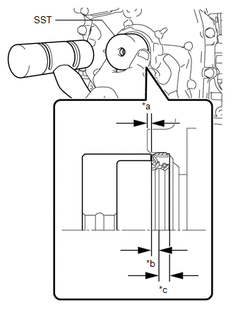
(a) w/o Side Lip:
(1) Apply MP grease to the lip of a new timing chain cover oil seal.
NOTICE:
- Do not allow foreign matter to contact the lip of the timing chain cover oil seal.
- Do not allow MP grease to contact the dust seal.
| (2) Using SST and a hammer, tap in the timing chain cover oil seal until the timing chain cover edge. SST: 09710-20011 09710-06071 Standard: -0.75 to -1.45 mm (-0.0295 to -0.0571 in.) (from edge of the timing chain cover assembly) NOTICE:
|
|
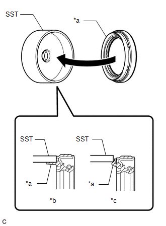
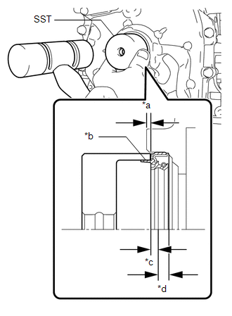
(b) w/ Side Lip:
(1) Apply MP grease to the lip of a new timing chain cover oil seal.
NOTICE:
- Keep the lip free from foreign matter.
- Do not allow MP grease to contact the dust seal.
- Do not allow MP grease to contact the side lip.
| (2) Fit the timing chain cover oil seal to SST. SST: 09710-20011 09710-06071 NOTICE: Visually check that the side lip is not caught on SST. |
|
| (3) Using SST and a plastic-faced hammer, tap in the timing chain cover oil seal. Standard depth: -0.75 to -1.45 mm (-0.0295 to -0.0571 in.) (From the edge of the timing chain cover assembly) NOTICE:
|
|
2. INSTALL CRANKSHAFT PULLEY ASSEMBLY
Click here .gif)
3. INSTALL FRONT SUSPENSION MEMBER REINFORCEMENT RH
Click here
4. INSTALL FAN AND GENERATOR V BELT
Click here
5. INSPECT FOR OIL LEAK
Click here
6. INSTALL NO. 1 ENGINE UNDER COVER ASSEMBLY
Click here
READ NEXT:
 Components
COMPONENTS ILLUSTRATION *1 FLYWHEEL SUB-ASSEMBLY *2 REAR ENGINE OIL SEAL *3 TRANSMISSION INPUT DAMPER ASSEMBLY - - N*m (kgf*cm, ft.*lbf): Specified torque ● Non-reusab
Removal
REMOVAL PROCEDURE 1. REMOVE HYBRID VEHICLE TRANSAXLE ASSEMBLY Click here 2. REMOVE TRANSMISSION INPUT DAMPER ASSEMBLY (a) Using SST, hold the crankshaft pulley assembly. SST: 09213-54015 SST: 09
SEE MORE:
Fail-safe Chart
FAIL-SAFE CHART ASC System (a) The stereo component equalizer assembly stores DTCs and freeze frame data and stops sound output if it detects any of the following abnormalities. Item Abnormality Detection Condition Fail-safe Control DTC Output Return Condition CAN communication malfun
Black Screen
PROCEDURE 1. CHECK DISPLAY SETTING (a) Check that the display is not in screen off mode. OK: The display setting is not in screen off mode. NG CHANGE SCREEN TO SCREEN ON MODE
OK 2. CHECK IMAGE QUALITY SETTING (a) Check that the display settings (contrast,
