Lexus NX: Inspection
INSPECTION
PROCEDURE
1. CHECK BRAKE CYLINDER AND PISTON
(a) Check the cylinder bore and piston for rust or scoring.
If necessary, replace the brake cylinder and piston.
2. CHECK PAD LINING THICKNESS
(a) Using a ruler, measure the pad lining thickness.
Standard thickness:
12.0 mm (0.472 in.)
Minimum thickness:
1.0 mm (0.0394 in.)
If the pad lining thickness is less than the minimum, replace the pad.
3. CHECK FRONT DISC BRAKE PAD SUPPORT PLATE
(a) Check the 4 plates as follows. If necessary, replace the plates.
(1) Use brake cleaner to clean the pad of the pad support plate and cylinder mounting contact surface. Inspect for deformation, cracks, rust and foreign matter that is difficult to remove.
(2) Use brake cleaner to clean the pad support plate contact surface of the cylinder mounting. After installing the pad support plate to the cylinder mounting, inspect for looseness and deformation.
(3) After installing the pad, check that the pad does not fall off easily (due to the spring force of the pad support plate being insufficient).
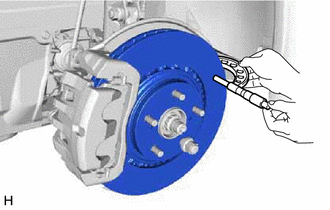
4. CHECK DISC THICKNESS
| (a) Using a micrometer, measure the disc thickness. Standard Thickness: 28.0 mm (1.102 in.) Minimum Thickness: 25.0 mm (0.984 in.) If the disc thickness is less than the minimum, replace the disc. |
|
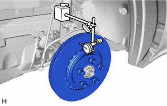
5. CHECK DISC RUNOUT
(a) Check the front axle hub bearing looseness (Click here .gif) ) and front axle hub runout (Click here ).
) and front axle hub runout (Click here ).
(b) Temporarily install the disc with the 5 hub nuts.
Torque:
103 N·m {1050 kgf·cm, 76 ft·lbf}
(c) Using a dial indicator, measure the disc runout 10.0 mm (0.394 in.) from the outer edge of the disc.
Maximum disc runout:
0.05 mm (0.00197 in.)
NOTICE:
Do not place the magnetic portion of the dial indicator near the axle hub or speed sensor.
If the runout is more than the maximum, change the installation positions of the disc and axle so that the runout is the smallest possible. If the runout is more than the maximum even when the installation positions are changed, grind the disc. If the disc thickness is less than the minimum, replace the disc.
(d) Remove the 5 hub nuts and disc.
READ NEXT:
 Reassembly
REASSEMBLY CAUTION / NOTICE / HINT HINT:
Use the same procedure for the RH and LH sides.
The following procedure is for the LH side.
PROCEDURE 1. TEMPORARILY INSTALL FRONT DISC BRAKE BLEEDER P
Installation
INSTALLATION CAUTION / NOTICE / HINT HINT:
Use the same procedure for the RH and LH sides.
The following procedure is for the LH side.
NOTICE: When the brake pedal is first depressed after rep
SEE MORE:
Components
COMPONENTS ILLUSTRATION *1 DECK FLOOR BOX LH *2 NO. 3 DECK BOARD SUB-ASSEMBLY *3 REAR DECK FLOOR BOX *4 NEGATIVE AUXILIARY BATTERY TERMINAL N*m (kgf*cm, ft.*lbf): Specified torque - - ILLUSTRATION *1 ECU INTEGRATION BOX RH *2 GLOVE COMPARTMENT DOOR ASSEMBL
G Sensor Failure (C1647)
DESCRIPTION The clearance warning sonar ECU assembly communicates with the airbag ECU assembly (yaw rate and acceleration sensor) via CAN communication, and if it is determined that the airbag ECU assembly (yaw rate and acceleration sensor) is malfunctioning, DTC C1647 is stored. DTC No. Detect
