Lexus NX: Installation
INSTALLATION
PROCEDURE
1. INSTALL NO. 2 ECM BRACKET
(a) Install the No. 2 ECM bracket to the ECM with the 2 screws.
Torque:
3.0 N·m {31 kgf·cm, 27 in·lbf}
2. INSTALL NO. 1 ECM BRACKET
(a) Install the No. 1 ECM bracket to the ECM with the 2 screws.
Torque:
3.0 N·m {31 kgf·cm, 27 in·lbf}
3. INSTALL ECM
(a) Install the ECM with the 3 bolts.
Torque:
for bolt A :
6.5 N·m {66 kgf·cm, 58 in·lbf}
for bolt B :
8.4 N·m {86 kgf·cm, 74 in·lbf}
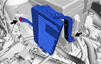
.png) | Bolt A |
 | Bolt B |
| (b) Connect the 2 ECM connectors and lock with the 2 levers. NOTICE:
|
|
(c) Connect the wire harness to the No. 2 ECM bracket with the bolt.
Torque:
8.4 N·m {86 kgf·cm, 74 in·lbf}
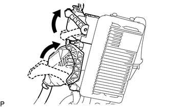
4. INSTALL AIR CLEANER CASE SUB-ASSEMBLY
(a) Install the air cleaner case sub-assembly with the 2 bolts.
Torque:
7.0 N·m {71 kgf·cm, 62 in·lbf}
5. INSTALL AIR CLEANER FILTER ELEMENT SUB-ASSEMBLY
(a) Install the air cleaner filter element sub-assembly to the air cleaner case sub-assembly.
6. INSTALL AIR CLEANER CAP SUB-ASSEMBLY
Click here .gif)
7. CONNECT CABLE TO NEGATIVE AUXILIARY BATTERY TERMINAL
NOTICE:
When disconnecting the cable, some systems need to be initialized after the cable is reconnected.
Click here
8. INSTALL DECK FLOOR BOX LH
Click here
9. INSTALL REAR DECK FLOOR BOX
Click here
10. INSTALL NO. 3 DECK BOARD SUB-ASSEMBLY
Click here
READ NEXT:
 Components
COMPONENTS ILLUSTRATION *1 ENGINE COOLANT TEMPERATURE SENSOR *2 NO. 1 ENGINE COVER SUB-ASSEMBLY *3 GROUND WIRE *4 GASKET N*m (kgf*cm, ft.*lbf) : Specified torque * For u
Removal
REMOVAL PROCEDURE 1. DRAIN ENGINE COOLANT Click here 2. REMOVE NO. 1 ENGINE COVER SUB-ASSEMBLY Click here 3. REMOVE ENGINE COOLANT TEMPERATURE SENSOR (a) Disconnect the engine coolant tempera
SEE MORE:
Light Sensor Circuit Malfunction (B1244)
DESCRIPTION The automatic light control sensor detects ambient light, converts it into an electrical signal and outputs it to the main body ECU (multiplex network body ECU). The main body ECU (multiplex network body ECU) turns the headlights and taillights on or off according to the signal. The main
Problem Symptoms Table
PROBLEM SYMPTOMS TABLE HINT:
Use the table below to help determine the cause of problem symptoms. If multiple suspected areas are listed, the potential causes of the symptoms are listed in order of probability in the "Suspected Area" column of the table. Check each symptom by checking the suspect
