Lexus NX: Installation
INSTALLATION
CAUTION / NOTICE / HINT
CAUTION:
As the engine assembly with transaxle is extremely heavy, the engine lifter may suddenly drop if the instructions listed in the repair manual are not followed. Therefore, always follow the instructions listed in the repair manual when performing this procedure.
HINT:
Perform "Inspection After Repairs" after replacing the engine assembly, cylinder head sub-assembly, camshaft, No. 2 camshaft, camshaft timing gear assembly, piston or piston ring.
Click here .gif)
PROCEDURE
1. INSTALL DRIVE SHAFT BEARING BRACKET
(a) Install the drive shaft bearing bracket with the 3 bolts.
Torque:
63.7 N·m {650 kgf·cm, 47 ft·lbf}
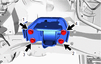
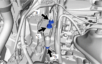
2. INSTALL ENGINE MOUNTING INSULATOR LH
HINT:
Perform this procedure only when replacement of the engine mounting insulator LH is necessary.
(a) Temporarily install the engine mounting insulator LH with the 4 bolts.
| (b) Tighten the 4 bolts in the sequence shown in the illustration. Torque: 95 N·m {969 kgf·cm, 70 ft·lbf} |
|
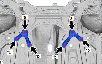
3. INSTALL ENGINE MOUNTING SPACER
HINT:
Perform this procedure only when replacement of the engine mounting spacer is necessary.
| (a) Temporarily install the engine mounting spacer with the 2 bolts. |
|
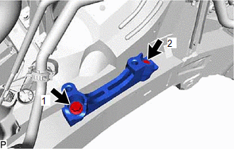
(b) Tighten the 2 bolts in the sequence shown in the illustration.
Torque:
95 N·m {969 kgf·cm, 70 ft·lbf}
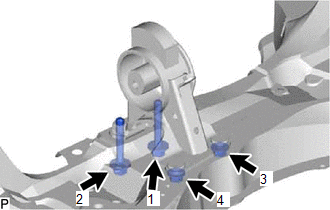
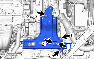
4. INSTALL ENGINE MOUNTING INSULATOR SUB-ASSEMBLY RH
HINT:
Perform this procedure only when replacement of the engine mounting insulator sub-assembly RH is necessary.
| (a) Temporarily install the engine mounting insulator sub-assembly RH with the 3 bolts. |
|

(b) Tighten the 3 bolts in the sequence shown in the illustration.
Torque:
95 N·m {969 kgf·cm, 70 ft·lbf}
(c) Install the radiator reservoir bracket with the bolt.
Torque:
5.0 N·m {51 kgf·cm, 44 in·lbf}
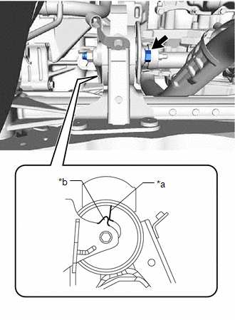
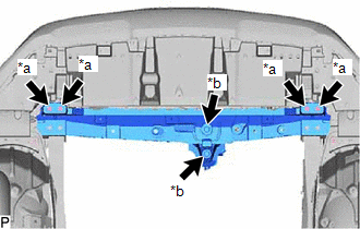
5. INSTALL REAR ENGINE MOUNTING INSULATOR
HINT:
Perform this procedure only when replacement of the rear engine mounting insulator is necessary.
| (a) Temporarily install the rear engine mounting insulator with the 2 bolts and 2 nuts. |
|
(b) Tighten the 2 bolts and 2 nuts in the sequence shown in the illustration.
Torque:
95 N·m {969 kgf·cm, 70 ft·lbf}
6. INSTALL ENGINE HANGER
Click here
7. REMOVE ENGINE FROM ENGINE STAND
NOTICE:
- Pay attention to the angle of the sling device as the engine assembly or engine hangers may be damaged or deformed if the angle is incorrect.
- With the exception of installing the engine assembly to an engine stand or removing the engine assembly from an engine stand, do not perform any work on the engine while it is suspended, as doing so is dangerous.
(a) Attach a sling device and hang the engine with a chain block.
(b) Lift the engine and remove it from the engine stand.
8. FIX ENGINE ASSEMBLY
Click here
9. INSTALL ENGINE WIRE
10. INSTALL FLYWHEEL SUB-ASSEMBLY
Click here
11. INSTALL TRANSMISSION INPUT DAMPER ASSEMBLY
Click here
12. TEMPORARILY INSTALL HYBRID VEHICLE TRANSAXLE ASSEMBLY
Click here
13. TIGHTEN HYBRID VEHICLE TRANSAXLE ASSEMBLY
Click here
14. INSTALL TRANSMISSION OIL COOLER ASSEMBLY
Click here
15. CONNECT WIRE HARNESS
Click here
16. INSTALL ENGINE ASSEMBLY WITH TRANSAXLE
(a) Temporarily install the front engine mounting insulator with the through bolt and nut.
| (b) Temporarily install the front suspension crossmember with the through bolt and nut. HINT: When installing the suspension crossmember, align the protrusion of the engine mounting bracket with the alignment mark of the engine mounting insulator. |
|
(c) Place the engine on an engine lifter.
NOTICE:
- Place the engine on wooden blocks or equivalent so that the engine is level.
-
To prevent coolant leaks, do not position the height adjustment attachments or plate lift attachments under the No. 2 motor water jacket cover assembly.
.png)
*1
No. 2 Motor Water Jacket Cover Assembly
(d) Operate the engine lifter and install the engine to the vehicle.
CAUTION:
Do not raise the engine more than necessary. If the engine is raised excessively, the vehicle may also be lifted up.
NOTICE:
- Make sure that the engine is clear of all wiring and hoses.
- While raising the engine into the vehicle, do not allow it to contact the vehicle.
| (e) Temporarily install the front suspension crossmember with the 2 bolts. |
|
.png)
| (f) Temporarily install the front suspension member rear brace RH and front suspension member rear brace LH with the 6 bolts. |
|
.png)
(g) Install the engine mounting insulator LH with the through bolt and nut.
Torque:
56 N·m {571 kgf·cm, 41 ft·lbf}
NOTICE:
While holding the through bolt in place, tighten the nut.
| (h) Install the engine mounting insulator RH with the bolt and 2 nuts. Torque: for bolt and nut A : 95 N·m {969 kgf·cm, 70 ft·lbf} for nut B : 52 N·m {530 kgf·cm, 38 ft·lbf} |
|
| (i) Tighten the 2 bolts. Torque: 137 N·m {1397 kgf·cm, 101 ft·lbf} |
|
| (j) Tighten the 6 bolts. Torque: for bolt A : 137 N·m {1397 kgf·cm, 101 ft·lbf} for bolt B : 93 N·m {948 kgf·cm, 69 ft·lbf} |
|
(k) Remove the 2 bolts and 2 engine hangers.
| (l) Install the front crossmember with the 6 bolts. Torque: for bolt A : 99 N·m {1010 kgf·cm, 73 ft·lbf} for bolt B : 95 N·m {969 kgf·cm, 70 ft·lbf} |
|
(m) While holding the nut in place, tighten the through bolt of the rear engine mounting insulator.
Torque:
95 N·m {969 kgf·cm, 70 ft·lbf}
HINT:
Check that the protrusion of the engine mounting bracket is aligned with the alignment mark of the engine mounting insulator.
(n) Tighten the through bolt and nut of the front engine mounting insulator.
Torque:
145 N·m {1479 kgf·cm, 107 ft·lbf}
NOTICE:
While holding the nut in place, tighten the through bolt.
17. INSTALL FRONT SUSPENSION MEMBER REINFORCEMENT LH
Click here
18. INSTALL FRONT SUSPENSION MEMBER REINFORCEMENT RH
Click here
19. INSTALL FRONT EXHAUST PIPE ASSEMBLY
Click here
20. INSTALL FLYWHEEL HOUSING UNDER COVER
(a) Install the flywheel housing under cover.
21. INSTALL FRONT DRIVE SHAFT HOLE SNAP RING LH
Click here
22. INSTALL FRONT DRIVE SHAFT ASSEMBLY LH
Click here
23. INSTALL FRONT DRIVE SHAFT ASSEMBLY RH
Click here
24. CONNECT FRONT LOWER NO. 1 SUSPENSION ARM SUB-ASSEMBLY LH
Click here
25. CONNECT FRONT LOWER NO. 1 SUSPENSION ARM SUB-ASSEMBLY RH
HINT:
Use the same procedure described for the LH side.
26. CONNECT TIE ROD END SUB-ASSEMBLY LH
Click here
27. CONNECT TIE ROD END SUB-ASSEMBLY RH
HINT:
Use the same procedure described for the LH side.
28. CONNECT FRONT STABILIZER LINK ASSEMBLY LH
Click here
29. CONNECT FRONT STABILIZER LINK ASSEMBLY RH
HINT:
Use the same procedure described for the LH side.
30. CONNECT FRONT SPEED SENSOR LH
Click here
31. CONNECT FRONT SPEED SENSOR RH
HINT:
Use the same procedure described for the LH side.
32. INSTALL FRONT AXLE SHAFT NUT LH
Click here
33. INSTALL FRONT AXLE SHAFT NUT RH
HINT:
Use the same procedure described for the LH side.
34. CONNECT NO. 1 STEERING COLUMN HOLE COVER SUB-ASSEMBLY
Click here
35. CONNECT NO. 2 STEERING INTERMEDIATE SHAFT ASSEMBLY
Click here
36. INSTALL COLUMN HOLE COVER SILENCER SHEET
Click here
37. CONNECT TRANSMISSION CONTROL CABLE ASSEMBLY
(a) Connect the transmission control cable assembly to the control shaft lever with the nut.
Torque:
12 N·m {122 kgf·cm, 9 ft·lbf}
(b) Connect the transmission control cable assembly to the control cable bracket with a new clip.
(c) Connect the transmission control cable assembly to the hybrid transaxle assembly with the bolt.
Torque:
12 N·m {122 kgf·cm, 9 ft·lbf}
(d) Connect the transmission control cable assembly to the rear engine mounting insulator with the bolt.
Torque:
5.0 N·m {51 kgf·cm, 44 in·lbf}
(e) Attach the clamp to connect the transmission control cable assembly to the bracket.
38. CONNECT HEATER WATER OUTLET HOSE
(a) Connect the heater water outlet hose to the No. 1 EGR pipe, and slide the hose clamp to secure the hose.
39. CONNECT HEATER WATER INLET HOSE
(a) Connect the heater water inlet hose to the cylinder head sub-assembly, and slide the hose clamp to secure the hose.
40. CONNECT FUEL TUBE SUB-ASSEMBLY
Click here
41. CONNECT WIRE HARNESS
(a) Install the terminal to the No. 1 engine room relay block side cover.
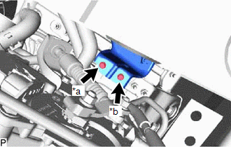
| (b) Connect the 3 connectors and attach the 2 claws to connect the wire harness to the No. 1 engine room relay block. |
|
.png)
(c) Install the nut.
Torque:
8.4 N·m {86 kgf·cm, 74 in·lbf}
| (d) Attach the 3 wire harness clamps and connect the wire harness with the bolt. Torque: 7.7 N·m {79 kgf·cm, 68 in·lbf} |
|
.png)
42. CONNECT GROUND WIRE
| (a) Connect the ground wire with the bolt and attach the 2 wire harness clamps. Torque: 29 N·m {296 kgf·cm, 21 ft·lbf} |
|
.png)
43. INSTALL NO. 5 INVERTER COOLING HOSE
(a) Install the No. 5 inverter cooling hose to the transmission oil cooler assembly, and slide the hose clip to secure the hose.
44. INSTALL NO. 3 INVERTER COOLING HOSE
(a) Install the No. 3 inverter cooling hose to the hybrid vehicle transaxle assembly, and slide the hose clip to secure the hose.
45. CONNECT SUCTION HOSE SUB-ASSEMBLY
Click here
46. CONNECT DISCHARGE HOSE SUB-ASSEMBLY
Click here
47. CONNECT NO. 1 RADIATOR HOSE
(a) Connect the No. 1 radiator hose to the cylinder head sub-assembly, and slide the hose clip to secure the hose.
48. INSTALL RADIATOR HOSE HOSE CLAMP
(a) Install the radiator hose hose clamp.
49. CONNECT NO. 2 RADIATOR HOSE
(a) Connect the No. 2 radiator hose to the water inlet, and slide the hose clip to secure the hose.
50. INSTALL FAN AND GENERATOR V BELT
Click here
51. CONNECT RADIATOR RESERVE TANK ASSEMBLY
(a) Connect the radiator reserve tank assembly with the 2 bolts.
Torque:
5.0 N·m {51 kgf·cm, 44 in·lbf}
52. INSTALL ECM
Click here
53. INSTALL INVERTER BRACKET ASSEMBLY
(a) Temporarily install the inverter bracket assembly with the 5 bolts.
| (b) Tighten the 5 bolts in the sequence shown in the illustration. Torque: 18 N·m {184 kgf·cm, 13 ft·lbf} |
|
54. INSTALL INVERTER WATER PUMP WITH MOTOR ASSEMBLY
| (a) Temporarily install the inverter water pump with motor assembly to the inverter bracket with bolt A. |
|
(b) Install bolt B.
Torque:
10 N·m {102 kgf·cm, 7 ft·lbf}
(c) Tighten bolt A.
Torque:
10 N·m {102 kgf·cm, 7 ft·lbf}
55. CONNECT NO. 2 FLOOR WIRE
CAUTION:
Be sure to wear insulated gloves.
(a) Connect the No. 2 floor wire to the hybrid vehicle transaxle assembly with the 2 clamps.
(b) Connect the No. 2 floor wire to the inverter bracket with the 2 clamps.
(c) Install the bolt.
Torque:
7.7 N·m {79 kgf·cm, 68 in·lbf}
56. INSTALL INVERTER WITH CONVERTER ASSEMBLY
Click here
57. INSTALL AIR CLEANER CASE SUB-ASSEMBLY
(a) Install the air cleaner case sub-assembly with the 2 bolts.
Torque:
7.0 N·m {71 kgf·cm, 62 in·lbf}
58. INSTALL AIR CLEANER FILTER ELEMENT SUB-ASSEMBLY
(a) Install the air cleaner filter element sub-assembly.
59. INSTALL AIR CLEANER CAP SUB-ASSEMBLY
Click here
60. INSTALL SERVICE PLUG GRIP
Click here
61. INSTALL HYBRID BATTERY SERVICE PLUG COVER
Click here
62. INSTALL BATTERY SERVICE HOLE COVER
Click here
63. CONNECT CABLE TO NEGATIVE AUXILIARY BATTERY TERMINAL
Click here
64. INITIALIZATION AFTER RECONNECTING AUXILIARY BATTERY TERMINAL
Click here
HINT:
When disconnecting and reconnecting the auxiliary battery, there is an automatic learning function that completes learning when the respective system is used.
Click here
65. INSTALL DECK FLOOR BOX LH
Click here
66. INSTALL REAR DECK FLOOR BOX
Click here
67. INSTALL NO. 3 DECK BOARD SUB-ASSEMBLY
Click here
68. ADD ENGINE OIL
Click here
69. ADD COOLANT (for Inverter Coolant)
Click here
70. ADD HYBRID TRANSAXLE FLUID
Click here
71. ADD ENGINE COOLANT
Click here
72. CHARGE AIR CONDITIONING SYSTEM WITH REFRIGERANT
Click here
73. INSPECT FOR FUEL LEAK
Click here
74. INSPECT FOR OIL LEAK
Click here
75. INSPECT FOR COOLANT LEAK
Click here
76. INSPECT FOR HYBRID TRANSAXLE FLUID
Click here
77. INSPECT FOR COOLANT LEAK (for Inverter Coolant)
Click here
78. INSPECT ENGINE OIL LEVEL
Click here
79. INSPECT ENGINE COOLANT LEVEL
Click here
80. INSPECT COOLANT LEVEL IN RESERVE TANK (for Inverter Coolant)
Click here
81. INSPECT HYBRID TRANSAXLE FLUID
Click here
82. INSPECT FOR EXHAUST GAS LEAK
Click here
83. INSPECT FOR REFRIGERANT LEAK
Click here
84. INSPECT IGNITION TIMING
Click here
85. INSPECT ENGINE IDLE SPEED
Click here
86. INSPECT CO/HC
Click here
87. TEST MODE PROCEDURE (SPEED SENSOR)
Click here
88. ADJUST SHIFT LEVER POSITION
Click here
89. ADJUST FRONT WHEEL ALIGNMENT
Click here
90. INSTALL FRONT FLOOR COVER CENTER LH
Click here
91. INSTALL REAR ENGINE UNDER COVER RH
(a) Install the rear engine under cover RH with the 4 clips.
92. INSTALL REAR ENGINE UNDER COVER LH
(a) Install the rear engine under cover LH with the 4 clips.
93. INSTALL NO. 1 ENGINE UNDER COVER ASSEMBLY
(a) Install the No. 1 engine under cover assembly with the 2 screws, 4 bolts and 3 clips.
94. INSTALL RADIATOR SUPPORT OPENING COVER
Click here
95. INSTALL NO. 1 ENGINE COVER SUB-ASSEMBLY
(a) Align the 3 grommets of the No. 1 engine cover sub-assembly with the 3 pins, and install the No. 1 engine cover sub-assembly by pressing it.
READ NEXT:
 Precaution
PRECAUTION HINT:
Any digits beyond the 0.01 mm (1/1000 in.) place for standard, minimum and maximum values should be used as a reference only.
When both standard and maximum or minimum values are
Components
COMPONENTS ILLUSTRATION *1 EXHAUST MANIFOLD CONVERTER SUB-ASSEMBLY *2 MANIFOLD STAY *3 NO. 1 EXHAUST MANIFOLD HEAT INSULATOR *4 NO. 2 EGR PIPE *5 NO. 2 MANIFOLD STAY *6 E
SEE MORE:
Removal
REMOVAL PROCEDURE 1. REMOVE FRONT FLOOR COVER CENTER LH Click here 2. REMOVE CHARCOAL CANISTER ASSEMBLY (a) Disconnect the connector from the canister pump module. *1 Vent Line Hose *2 Air Inlet Line Hose *3 Purge Line Hose *4 Retainer *a Pull Out
Hybrid transmission
Select the shift position depending
on your purpose and situation.
Shift position purpose and functions
*1: To improve fuel efficiency and reduce
noise, shift the shift lever to D for normal
driving.
You can choose gear range suitable for
your driving situation by operating the
paddle shif
