Lexus NX: Installation
INSTALLATION
PROCEDURE
1. INSTALL HV WATER PUMP BRACKET SUB-ASSEMBLY
| (a) Temporarily install the HV water pump bracket sub-assembly to the inverter bracket with bolt A. |
|
(b) Install bolt B.
Torque:
10 N·m {102 kgf·cm, 7 ft·lbf}
(c) Tighten bolt A.
Torque:
10 N·m {102 kgf·cm, 7 ft·lbf}
2. INSTALL WATER PUMP WITH MOTOR
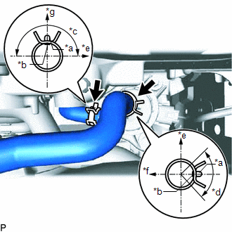
| (a) Connect the No. 2 inverter cooling hose and No. 3 inverter cooling hose to the water pump with motor, and slide the clamp to secure it. NOTICE:
|
|
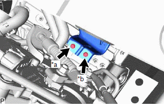
(b) Install the water pump with motor with the 3 bolts.
Torque:
6.1 N·m {62 kgf·cm, 54 in·lbf}
HINT:
First, temporarily install the 2 bolts, install the 3rd bolt with the specified torque, and then tighten the 2 bolts.
(c) Connect the water pump with motor connector.
3. CONNECT NO. 2 INVERTER COOLING HOSE ASSEMBLY
Click here .gif)
4. INSTALL UPPER RADIATOR SUPPORT SUB-ASSEMBLY
Click here
5. ADD COOLANT (for Inverter Coolant)
Click here
6. INSPECT FOR COOLANT LEAK (for Inverter Coolant)
Click here
7. INSTALL NO. 1 ENGINE UNDER COVER ASSEMBLY
Click here
READ NEXT:
 Components
COMPONENTS ILLUSTRATION *1 INVERTER RESERVOIR ASSEMBLY *2 NO. 1 ENGINE COVER SUB-ASSEMBLY *3 WIRE HARNESS - - N*m (kgf*cm, ft.*lbf): Specified torque - - ILLUSTRATION
SEE MORE:
Dtc Check / Clear
DTC CHECK / CLEAR CHECK FOR DTC (a) Turn the power switch off. (b) Connect the Techstream to the DLC3. (c) Turn the power switch on (IG). (d) Turn the Techstream on. (e) Enter the following menus: Body Electrical / Back Door / Trouble Codes. (f) Check for DTCs. Click here Body Electrical > Back
One or more Power Seat Motors do not Operate
DESCRIPTION Signals are input into the front power seat switch LH. The built-in ECU manages the signals received from the front power seat switch LH, and operates each motor. If the front power seat switch LH receives more than 2 motor operation signals, the motor is stopped. Manual operation is res
