- Inverter W/P Revolution
- (Inverter) W/P Run Control Duty
- Ready Signal
Lexus NX: Motor Electronics Coolant Pump "A" Control Performance (P0C73-776)
Lexus NX Service Manual / Engine & Hybrid System / 2ar-fxe (hybrid / Battery Control) / Hybrid Control System / Motor Electronics Coolant Pump "A" Control Performance (P0C73-776)
DESCRIPTION
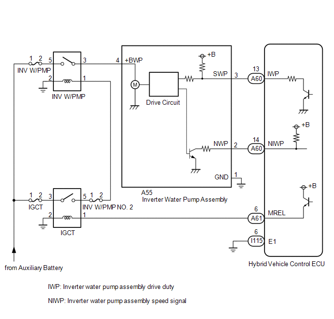
The inverter water pump assembly transmits rotation speed information to the hybrid vehicle control ECU. The hybrid vehicle control ECU monitors the speed and detects malfunctions.
| DTC No. | Detection Item | DTC Detection Condition | Trouble Area | MIL | Warning Indicate |
|---|---|---|---|---|---|
| P0C73-776 | Motor Electronics Coolant Pump "A" Control Performance | The inverter water pump assembly revolution speed is abnormally high or low (or stop) for 1 minute or more. Or the inverter water pump assembly stops intermittently after abnormal revolution speed is detected. (1 trip detection logic) |
| Comes on | Master Warning Light: Comes on |
HINT:
The inverter water pump assembly operates when the power switch is on (READY).
Related Data List| DTC No. | ECU Data List |
|---|---|
| P0C73-776 | |
| DTC No. | Active Test |
|---|---|
| P0C73-776 | Activate the (Inverter) Water Pump |
MONITOR DESCRIPTION
The hybrid vehicle control ECU monitors speed of the inverter water pump assembly. If there is an abnormality in speed, the hybrid vehicle control ECU will illuminate the MIL and store a DTC.
MONITOR STRATEGY
| Related DTCs | P0C73 (INF 776): Water pump malfunction |
| Required sensors/components | Inverter water pump assembly |
| Frequency of operation | Continuous |
| Duration | TMC's intellectual property |
| MIL operation | 1 driving cycle |
| Sequence of operation | None |
TYPICAL ENABLING CONDITIONS
| The monitor will run whenever the following DTCs are not stored | TMC's intellectual property |
| Other conditions belong to TMC's intellectual property | - |
TYPICAL MALFUNCTION THRESHOLDS
| TMC's intellectual property | - |
COMPONENT OPERATING RANGE
| Hybrid vehicle control ECU | DTC P0C73 (INF 776) is not detected |
CONFIRMATION DRIVING PATTERN
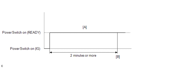
- Connect the Techstream to the DLC3.
- Turn the power switch on (IG) and turn the Techstream on.
- Clear the DTCs (even if no DTCs are stored, perform the clear DTC procedure).
- Turn the power switch off and wait for 30 seconds or more.
- Turn the power switch on (IG) and turn the Techstream on.
- Turn the power switch on (READY). [A]
- Wait for 2 minutes or more.
- Enter the following menus: Powertrain / Hybrid Control / Trouble Codes. [B]
-
Read the current DTCs.
HINT:
- If a current DTC is output, the system is malfunctioning.
- If current DTCs are not output, perform the following steps to check for permanent DTCs.
- Check that the permanent DTCs are cleared.
- If the permanent DTCs are not cleared, perform a universal trip, and then check for permanent DTCs again.
WIRING DIAGRAM
CAUTION / NOTICE / HINT
NOTICE:
- If DTC P0A78-284, 286, P0A79-692, 696, P0A7A-322, 324, P0A94-553 or 557 is output, replace the inverter with converter assembly after this inspection.
-
If this vehicle is jump started, etc. and excessive voltage is applied to the auxiliary battery, the inverter water pump assembly may suspend control as a self-protection function and store DTC.
(When the auxiliary battery voltage returns to normal, the inverter water pump assembly will resume normal operation. In this case it is not necessary to replace the inverter water pump assembly.)
-
If air enters the system while bleeding air during coolant exchange, etc. and the inverter water pump assembly revolution speed becomes abnormally high, the inverter water pump assembly may suspend control as a fail-safe function and the hybrid vehicle control ECU may store this DTC.
(When air bleeding is complete, the inverter water pump assembly will resume normal operation. In this case, it is not necessary to replace the inverter water pump assembly.)
HINT:
After the repair, clear the DTCs and perform the following procedure to check that DTCs are not output.
- Turn the power switch on (READY) and wait for 2 minutes or more.
PROCEDURE
| 1. | CHECK QUANTITY OF HV COOLANT |
Click here .gif)
| Result | Proceed to |
|---|---|
| No leaks are found and the HV coolant level in the inverter reserve tank assembly is above the low line. | A |
| No leaks are found and the HV coolant level in the inverter reserve tank assembly is below the low line. | B |
| HV coolant leaks are evident. | C |
| B | .gif) | ADD HV COOLANT |
| C | | INSPECT FOR HV COOLANT LEAK |
|
.gif)
| 2. | CHECK COOLANT HOSE |
Click here
| NG | | REPAIR OR REPLACE COOLANT HOSE |
|
| 3. | READ VALUE USING TECHSTREAM (INVERTER W/P REVOLUTION) |
NOTICE:
Be sure to perform the inspection with the auxiliary battery voltage at 11 V or more.
HINT:
- When the auxiliary battery voltage is low, the inverter water pump assembly may not operate.
- When the inverter water pump assembly signal line (SWP - IWP) is open or its connection is faulty, the inverter water pump assembly is operated forcibly.
(a) Connect the Techstream to the DLC3.
(b) Turn the power switch on (IG).
(c) Enter the following menus: Powertrain / Hybrid Control / Data List / Inverter W/P Revolution.
Powertrain > Hybrid Control > Data List| Tester Display |
|---|
| Inverter W/P Revolution |
(d) Read the Data List.
| Tester Display | Condition | Specified Condition |
|---|---|---|
| Inverter W/P Revolution | Power switch on (IG) | 625 rpm or less |
HINT:
When the inverter water pump assembly is not operating, the Data List item "Inverter W/P Revolution" displays a value lower than 625 rpm.
(e) Turn the power switch off.
| NG | | GO TO STEP 7 |
|
| 4. | CLEAR DTC |
Click here
|
| 5. | READ VALUE USING TECHSTREAM (ACTIVATE THE (INVERTER) WATER PUMP) |
NOTICE:
Be sure to perform the inspection with the auxiliary battery voltage at 11 V or more.
HINT:
When the auxiliary battery voltage is low, the inverter water pump assembly may not operate.
(a) Connect the Techstream to the DLC3.
(b) Turn the power switch on (IG).
(c) Enter the following menus: Powertrain / Hybrid Control / Active Test / Activate the (Inverter) Water Pump.
Powertrain > Hybrid Control > Active Test| Tester Display |
|---|
| Activate the (Inverter) Water Pump |
(d) Select "Inverter W/P Revolution" in the Data List.
Powertrain > Hybrid Control > Data List| Tester Display |
|---|
| Inverter W/P Revolution |
(e) While performing the "Activate the (Inverter) Water Pump" Active Test, check "Inverter W/P Revolution" in the Data List.
| Tester Display | Condition | Specified Condition |
|---|---|---|
| Inverter W/P Revolution | Power switch on (IG) | 2250 to 5625 rpm |
HINT:
- Perform the Active Test with the inverter coolant temperature between -15 and 65°C (5 to 149°F).
- When the inverter water pump assembly is not operating, the Data List item "Inverter W/P Revolution" displays a value lower than 625 rpm.
(f) Turn the power switch off.
| NG | | GO TO STEP 7 |
|
| 6. | CHECK HV COOLANT (CHECK FOR CONDITIONS THAT MAY HAVE CAUSED FREEZING) |
Click here
| Result | Proceed to |
|---|---|
| Ambient Temperature value is above freezing temperature of the HV coolant. | A |
| Ambient Temperature value is below freezing temperature of the HV coolant. | B |
| A | | REPLACE INVERTER WATER PUMP ASSEMBLY |
| B | | REPLACE HV COOLANT |
| 7. | CHECK CONNECTOR CONNECTION CONDITION (HYBRID VEHICLE CONTROL ECU CONNECTOR) |
Click here
| NG | | CONNECT SECURELY |
|
| 8. | CHECK CONNECTOR CONNECTION CONDITION (INVERTER WATER PUMP ASSEMBLY CONNECTOR) |
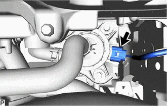
| (a) Check the connector connections and contact pressure of the relevant terminals for the inverter water pump assembly connector. Click here OK: The connector is connected securely and there are no contact problems. |
|
| NG | | CONNECT SECURELY |
|
| 9. | CHECK HARNESS AND CONNECTOR (HYBRID VEHICLE CONTROL ECU - INVERTER WATER PUMP ASSEMBLY) |
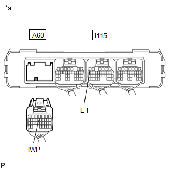
(a) Disconnect the A60 hybrid vehicle control ECU connector.
(b) Disconnect the A55 inverter water pump assembly connector.
(c) Measure the resistance according to the value(s) in the table below.
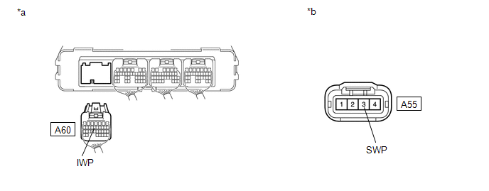
| *a | Rear view of wire harness connector (to Hybrid Vehicle Control ECU) | *b | Front view of wire harness connector (to Inverter Water Pump Assembly) |
Standard Resistance (Check for Open):
| Tester Connection | Condition | Specified Condition |
|---|---|---|
| A60-13 (IWP) - A55-3 (SWP) | Power switch off | Below 1 Ω |
Standard Resistance (Check for Short):
| Tester Connection | Condition | Specified Condition |
|---|---|---|
| A60-13 (IWP) or A55-3 (SWP) - Body ground and other terminals | Power switch off | 10 kΩ or higher |
(d) Reconnect the A55 inverter water pump assembly connector.
(e) Reconnect the A60 hybrid vehicle control ECU connector.
| NG | | REPAIR OR REPLACE HARNESS OR CONNECTOR |
|
| 10. | READ VALUE USING TECHSTREAM (INVERTER W/P REVOLUTION) |
NOTICE:
Be sure to perform the inspection with the auxiliary battery voltage at 11 V or more.
HINT:
When the auxiliary battery voltage is low, the inverter water pump assembly may not operate.
(a) Connect the Techstream to the DLC3.
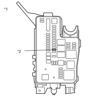
| (b) Remove the INV W/PMP fuse from No. 1 engine room relay block. |
|
(c) Turn the power switch on (IG).
(d) Enter the following menus: Powertrain / Hybrid Control / Data List / Inverter W/P Revolution.
Powertrain > Hybrid Control > Data List| Tester Display |
|---|
| Inverter W/P Revolution |
(e) Read the Data List.
| Tester Display | Condition | Specified Condition |
|---|---|---|
| Inverter W/P Revolution | Power switch on (IG) | 125 rpm or less |
(f) Turn the power switch off.
(g) Install the INV W/PMP fuse.
| NG | | REPLACE HYBRID VEHICLE CONTROL ECU |
|
| 11. | CHECK HARNESS AND CONNECTOR (HYBRID VEHICLE CONTROL ECU - INVERTER WATER PUMP ASSEMBLY) |
(a) Disconnect the A60 hybrid vehicle control ECU connector.
(b) Turn the power switch on (IG).
| (c) Measure the voltage according to the value(s) in the table below. Standard Voltage:
NOTICE: Turning the power switch on (IG) with the hybrid vehicle control ECU connector disconnected causes other DTCs to be stored. Clear the DTCs after performing this inspection. |
|
(d) Turn the power switch off.
(e) Reconnect the A60 hybrid vehicle control ECU connector.
| NG | | REPLACE INVERTER WATER PUMP ASSEMBLY |
|
| 12. | CHECK HYBRID VEHICLE CONTROL ECU (CHECK WAVEFORM) |
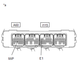
(a) Connect an oscilloscope between the hybrid vehicle control ECU terminals specified in the table below.
(b) Turn the power switch on (IG).
| (c) While turning the power switch on (IG), check the waveform between the hybrid vehicle control ECU terminals.
OK: Waveform duty ratio is between 3% and 9%. |
|
(d) Turn the power switch off.
| OK | | REPLACE INVERTER WATER PUMP ASSEMBLY |
| NG | | REPLACE HYBRID VEHICLE CONTROL ECU |
READ NEXT:
 Hybrid Battery System Discharge Time Too Long (P0C76-523)
DTC SUMMARY MALFUNCTION DESCRIPTION The hybrid vehicle control ECU detects that the electrical charge stored in the high-voltage condenser of the inverter with converter assembly cannot be discharged.
DC/DC Converter Step Up Voltage Performance (P0CA3-442)
DTC SUMMARY MALFUNCTION DESCRIPTION This DTC indicates that it has been detected that the VH voltage cannot be boosted as commanded due to malfunction of the boost converter system. The cause of this
Drive Motor "A" Inverter Voltage Sensor Circuit Range / Performance (P0D2E-565)
DTC SUMMARY MALFUNCTION DESCRIPTION VH voltage sensor signal malfunction in the inverter for the motor. Internal inverter malfunction
Internal circuit malfunction in the inverter for the motor
Ma
SEE MORE:
Inspection
INSPECTION PROCEDURE 1. CHECK BRAKE CYLINDER AND PISTON (a) Check the cylinder bore and piston for rust or scoring. If necessary, replace the disc brake cylinder and piston. 2. CHECK PAD LINING THICKNESS (a) Using a ruler, measure the pad lining thickness. Standard thickness: 10.0 mm (0.394 in.) Mi
Seat Heater Switch Circuit
DESCRIPTION When the refreshing seat switch is operated, the air conditioning amplifier assembly receives the signal via the LIN communication line, and operates the seat heater for the corresponding rear seat. WIRING DIAGRAM CAUTION / NOTICE / HINT NOTICE:
If the auxiliary battery voltage is l
© 2016-2026 Copyright www.lexunx.com
