Lexus NX: Installation
INSTALLATION
PROCEDURE
1. INSTALL INTAKE MANIFOLD
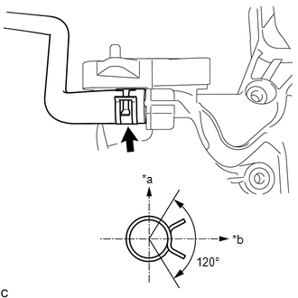
| (a) Connect the purge line hose to the intake manifold, and slide the clamp to secure the hose. HINT: Make sure the hose clamp is oriented as shown in the illustration. |
|
(b) Install the vacuum hose to the intake manifold.
(c) Install the wiring harness clamp bracket with the bolt.
Torque:
10 N·m {102 kgf·cm, 7 ft·lbf}
(d) Install a new No. 1 intake manifold to head gasket to the intake manifold.
(e) Install the intake manifold to the vehicle.
2. INSTALL FUEL DELIVERY PIPE
Click here .gif)
3. CONNECT FUEL TUBE SUB-ASSEMBLY
Click here
4. CONNECT NO. 1 EGR PIPE
(a) Install a new gasket to the No. 1 EGR pipe.
NOTICE:
Make sure the claws of the gasket face the No. 1 EGR pipe.
(b) Temporarily install the No. 1 EGR pipe with the 3 bolts and nut.
(c) Tighten the 3 bolts and nut to connect the No. 1 EGR pipe.
Torque:
21 N·m {214 kgf·cm, 15 ft·lbf}
5. CONNECT INTAKE MANIFOLD
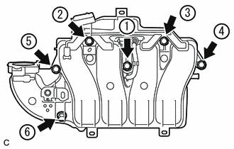
(a) Temporarily install the intake manifold with the 6 bolts.
| (b) Tighten the 6 bolts in the order shown in the illustration. Torque: 28 N·m {286 kgf·cm, 21 ft·lbf} |
|
(c) Connect the No. 2 PCV hose to the intake manifold, and slide the clamp to secure the hose.
6. CONNECT ENGINE WIRE
(a) Attach the 6 clamps and connect the engine wire.
(b) Connect the heated oxygen sensor connector.
7. INSTALL MANIFOLD ABSOLUTE PRESSURE SENSOR
Click here
8. INSTALL EGR VALVE ASSEMBLY
Click here
9. INSTALL AIR CLEANER CASE SUB-ASSEMBLY
Click here
10. INSTALL AIR CLEANER FILTER ELEMENT SUB-ASSEMBLY
Click here
11. INSTALL OUTER COWL TOP PANEL
(a) Install the outer cowl top panel with the 13 bolts.
Torque:
5.5 N·m {56 kgf·cm, 49 in·lbf}
(b) Attach the 4 clamps and connect the wire harness.
(c) Connect the connector.
12. INSTALL SUSPENSION TOWER DAMPER
-
w/ Performance Damper:
Click here
-
w/o Performance Damper:
Click here
13. INSTALL WINDSHIELD WIPER MOTOR ASSEMBLY
Click here
14. INSTALL THROTTLE WITH MOTOR BODY ASSEMBLY
Click here
15. CONNECT CABLE TO NEGATIVE AUXILIARY BATTERY TERMINAL
16. INITIALIZATION AFTER RECONNECTING AUXILIARY BATTERY TERMINAL
Click here
HINT:
When disconnecting and reconnecting the auxiliary battery, there is an automatic learning function that completes learning when the respective system is used.
Click here
17. INSTALL DECK FLOOR BOX LH
Click here
18. INSTALL REAR DECK FLOOR BOX
Click here
19. INSTALL NO. 3 DECK BOARD SUB-ASSEMBLY
Click here
20. ADD ENGINE COOLANT
Click here
21. INSPECT FOR COOLANT LEAK
Click here
22. INSPECT FOR FUEL LEAK
Click here
READ NEXT:
 Intake System
On-vehicle InspectionON-VEHICLE INSPECTION PROCEDURE 1. INSPECT INTAKE SYSTEM HINT: Perform "Inspection After Repair" after repairing air leaks in the intake system. Click here (a) Check that there
Engine Oil Cooler
ComponentsCOMPONENTS ILLUSTRATION *1 OIL COOLER ASSEMBLY *2 GASKET *3 SEAL WASHER *4 UNION BOLT N*m (kgf*cm, ft.*lbf): Specified torque ● Non-reusable part Remova
SEE MORE:
Removal
REMOVAL CAUTION / NOTICE / HINT NOTICE: While the auxiliary battery is connected, even if the power switch is off, the brake control system activates when the brake pedal is depressed or any door courtesy switch turns on. Therefore, when servicing the brake system components, do not operate the brak
How To Proceed With Troubleshooting
CAUTION / NOTICE / HINT HINT:
Use the following procedure to troubleshoot the ASC system.
*: Use the Techstream.
PROCEDURE 1. VEHICLE BROUGHT TO WORKSHOP
NEXT 2. CUSTOMER PROBLEM ANALYSIS AND SYMPTOM CHECK
NEXT 3. INSPECT AUXILIARY BA
