Lexus NX: Removal
REMOVAL
PROCEDURE
1. REMOVE FAN SHROUD WITH COOLING FAN
Click here .gif)
2. REMOVE COOLING FAN WIRE
| (a) Disconnect the cooling fan ECU connector. |
|
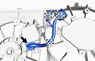
(b) Detach the 3 clamps and remove the cooling fan wire.
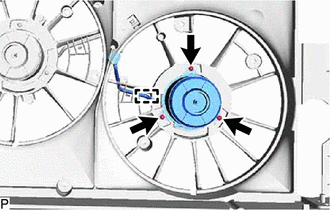
3. REMOVE COOLING FAN ECU
| (a) Disconnect the cooling fan motor connector and No. 2 cooling fan motor connector. |
|
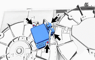
(b) Remove the 2 screws and cooling fan ECU.
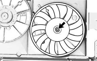
4. REMOVE FAN
| (a) Remove the nut and fan. |
|
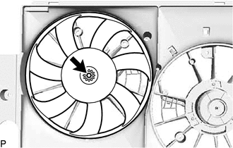
5. REMOVE NO. 2 FAN
| (a) Remove the nut and No. 2 fan. |
|
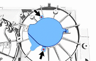
6. REMOVE COOLING FAN MOTOR
(a) Detach the clamp, and remove the 3 screws and cooling fan motor.
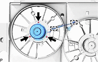
7. REMOVE NO. 2 COOLING FAN MOTOR
| (a) Remove the 2 screws and cooling fan motor insulator from the fan shroud. |
|
| (b) Detach the 2 clamps, and remove the 3 screws and No. 2 cooling fan motor. |
|
READ NEXT:
 Installation
INSTALLATION PROCEDURE 1. INSTALL NO. 2 COOLING FAN MOTOR (a) Attach the 2 clamps and install the No. 2 cooling fan motor with the 3 screws. Torque: 3.9 N·m {40 kgf·cm, 35 in·lbf} (b) Install the
Parts Location
PARTS LOCATION ILLUSTRATION *1 COOLING FAN RELAY (FAN NO. 1) *2 COOLING FAN ECU *3 COOLING FAN MOTOR *4 CRANKSHAFT POSITION SENSOR *5 ECM *6 NO. 2 ENGINE ROOM RELAY BLOCK
SEE MORE:
Removal
REMOVAL PROCEDURE 1. REMOVE NO. 2 FORWARD RECOGNITION COVER Click here 2. REMOVE NO. 1 FORWARD RECOGNITION COVER Click here 3. REMOVE INNER REAR VIEW MIRROR ASSEMBLY (a) Disconnect the connector. *a Connector *b Screw (b) Detach the clamp. (c) Using a T20 "TORX
Hybrid Battery Pack Sensor Module (P0AFC-150)
DESCRIPTION The hybrid vehicle control ECU alerts the driver and performs fail-safe control based on error signals sent from the battery voltage sensor. DTC No. Detection Item DTC Detection Condition Trouble Area MIL Warning Indicate P0AFC-150 Hybrid Battery Pack Sensor Module A
© 2016-2026 Copyright www.lexunx.com
