Lexus NX: Power Switch
Components
COMPONENTS
ILLUSTRATION
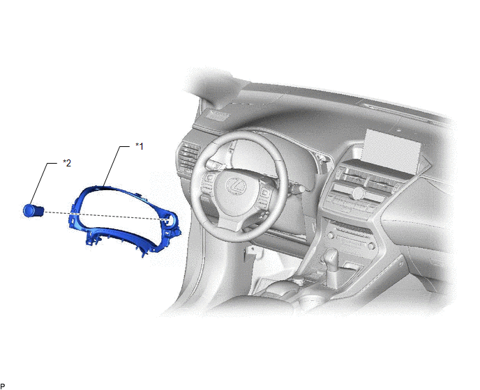
| *1 | INSTRUMENT CLUSTER FINISH PANEL SUB-ASSEMBLY | *2 | POWER SWITCH |
Removal
REMOVAL
PROCEDURE
1. REMOVE INSTRUMENT CLUSTER FINISH PANEL SUB-ASSEMBLY
Click here .gif)
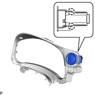
2. REMOVE POWER SWITCH
| (a) Detach the 2 claws and remove the power switch. |
|
Inspection
INSPECTION
PROCEDURE
1. INSPECT POWER SWITCH
| (a) Measure the resistance according to the value(s) in the table below. Standard Resistance:
If the result is not as specified, replace the power switch. |
|
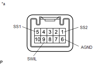
(b) Apply battery voltage between the terminals of the power switch, and check the illumination condition of the power switch.
OK:
| Measurement Condition | Specified Condition |
|---|---|
| Battery positive (+) → Terminal 9 (SWIL) Battery negative (-) → Terminal 6 (AGND) | Illuminates |
NOTICE:
- If the positive (+) lead and the negative (-) lead are incorrectly connected, the power switch indicator will not illuminate.
- If the voltage is too low, the indicator will not illuminate.
If the result is not as specified, replace the power switch.
Installation
INSTALLATION
PROCEDURE
1. INSTALL POWER SWITCH
(a) Attach the 2 claws to install the power switch.
2. INSTALL INSTRUMENT CLUSTER FINISH PANEL SUB-ASSEMBLY
Click here .gif)
READ NEXT:
 Camera Heater
ComponentsCOMPONENTS ILLUSTRATION *1 FORWARD RECOGNITION WITH HEATER HOOD SUB-ASSEMBLY - - RemovalREMOVAL PROCEDURE 1. REMOVE FORWARD RECOGNITION CAMERA Click here 2. REMOVE FORWARD R
SEE MORE:
Generator Temperature Sensor Circuit Range / Performance (P0A37-260,P0A3A-258)
DESCRIPTION The resistance of the thermistor built into the generator temperature sensor changes in accordance with changes in generator (MG1) temperature. The lower the generator (MG1) temperature, the higher the thermistor resistance. Conversely, the higher the generator (MG1) temperature, the low
ICS Detection Area Adjustment Incomplete (C1AF0)
DESCRIPTION When ICS detection area adjustment is incomplete, the clearance warning ECU assembly stores DTC C1AF0. DTC No. Detection Item DTC Detection Condition Trouble Area C1AF0 ICS Detection Area Adjustment Incomplete ICS detection area adjustment incomplete
Intelligent cle
