
Lexus NX: Installation
INSTALLATION
PROCEDURE
1. INSTALL AUXILIARY BATTERY
(a) Install the auxiliary battery.
| (b) Install the battery insulator to the auxiliary battery. |
|
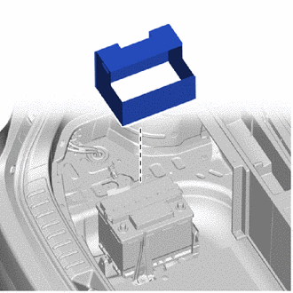
(c) Install the L-shaped pipe section to the auxiliary battery without twisting the battery hose.
HINT:
Insert the auxiliary battery hose all the way into the auxiliary battery.
(d) Install the battery clamp sub-assembly to the auxiliary battery with the bolt and nut.
Torque:
for bolt :
16.5 N·m {168 kgf·cm, 12 ft·lbf}
for nut :
4.9 N·m {50 kgf·cm, 43 in·lbf}
(e) Attach the clamp and connect the wire harness.
(f) Connect the cable to the positive (+) auxiliary battery terminal and tighten the nut.
Torque:
5.4 N·m {55 kgf·cm, 48 in·lbf}
(g) Attach the claw to close the auxiliary battery terminal cap.
2. CONNECT CABLE TO NEGATIVE AUXILIARY BATTERY TERMINAL
NOTICE:
When disconnecting the cable, some systems need to be initialized after the cable is reconnected.
3. INSTALL DECK FLOOR BOX LH
Click here .gif)
4. INSTALL NO. 3 DECK BOARD SUB-ASSEMBLY
Click here
5. INSTALL DECK BOARD ASSEMBLY
Click here
READ NEXT:
 Battery Thermometer Sensor
On-vehicle InspectionON-VEHICLE INSPECTION PROCEDURE 1. INSPECT THERMISTOR ASSEMBLY (a) Disconnect the thermistor assembly connector. *a Component without harness connected (Thermis
Precaution
PRECAUTION CAUTION:
Before inspecting the high-voltage system or disconnecting the low voltage connector of the inverter with converter assembly, take safety precautions such as wearing insulated g
SEE MORE:
Problem Symptoms Table
PROBLEM SYMPTOMS TABLE NOTICE:
When replacing the combination meter assembly, always replace it with a new one. If a combination meter assembly which was installed to another vehicle is used, the information stored in it will not match the information from the vehicle and a DTC may be stored.
I
Odo/Trip Switch Malfunction
DESCRIPTION The ODO/TRIP display of the combination meter changes each time the trip switch is pressed. WIRING DIAGRAM CAUTION / NOTICE / HINT NOTICE: When replacing the combination meter assembly, make sure to replace it with a new one. PROCEDURE 1. READ VALUE USING TECHSTREAM (ODO/TRIP CHAN
