Lexus NX: Battery Thermometer Sensor
On-vehicle Inspection
ON-VEHICLE INSPECTION
PROCEDURE
1. INSPECT THERMISTOR ASSEMBLY
| (a) Disconnect the thermistor assembly connector. |
|
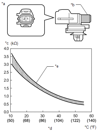
(b) Measure the resistance according to the value(s) in the table below.
Standard Resistance:
| Tester Connection | Condition | Specified Condition |
|---|---|---|
| 1 - 2 | 10°C (50°F) | 3.00 to 3.73 kΩ |
| 1 - 2 | 15°C (59°F) | 2.45 to 2.88 kΩ |
| 1 - 2 | 20°C (68°F) | 1.95 to 2.30 kΩ |
| 1 - 2 | 25°C (77°F) | 1.60 to 1.80 kΩ |
| 1 - 2 | 30°C (86°F) | 1.28 to 1.47 kΩ |
| 1 - 2 | 35°C (95°F) | 1.00 to 1.22 kΩ |
| 1 - 2 | 40°C (104°F) | 0.80 to 1.00 kΩ |
| 1 - 2 | 45°C (113°F) | 0.65 to 0.85 kΩ |
| 1 - 2 | 50°C (122°F) | 0.50 to 0.70 kΩ |
| 1 - 2 | 55°C (131°F) | 0.44 to 0.60 kΩ |
| 1 - 2 | 60°C (140°F) | 0.36 to 0.50 kΩ |
NOTICE:
- Hold the sensor only by its connector. Touching the sensor may change the resistance value.
- When measuring, the sensor temperature must be the same as the ambient temperature.
HINT:
As the temperature increases, the resistance decreases (see the graph).
If the resistance is not as specified, replace the thermistor assembly.
READ NEXT:
 Precaution
PRECAUTION CAUTION:
Before inspecting the high-voltage system or disconnecting the low voltage connector of the inverter with converter assembly, take safety precautions such as wearing insulated g
System Diagram
SYSTEM DIAGRAM
SEE MORE:
Unable To Connect To Call Center
DESCRIPTION This may occur when the intensity of telephone radio frequency was very weak or the safety connect system has a malfunction and a DTC is stored. PROCEDURE 1. CHECK COMMUNICATION SERVICE CONDITION (a) Move the vehicle. (1) If the vehicle is outside the communication service area,
Initialization
INITIALIZATION INITIALIZE SLIDING ROOF SYSTEM NOTICE:
When the roof glass is adjusted or removed/installed, or the sliding roof drive gear sub-assembly is replaced, the glass position cannot be determined and the sliding roof drive gear sub-assembly must be initialized (pulse sensor initial posit
