Lexus NX: Installation
INSTALLATION
CAUTION / NOTICE / HINT
HINT:
- Use the same procedure for the RH and LH sides.
- The procedure listed below is for the LH side.
PROCEDURE
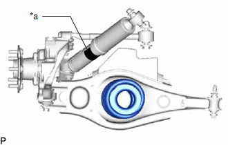
1. TEMPORARILY INSTALL REAR NO. 1 SHOCK ABSORBER BRACKET LH
| (a) Temporarily install the rear No. 1 shock absorber bracket LH to the rear shock absorber assembly LH with the bolt and nut. NOTICE: Make sure the identification label of the rear shock absorber assembly LH is facing the vehicle rear. |
|
2. TEMPORARILY INSTALL REAR SHOCK ABSORBER ASSEMBLY LH
| (a) Support the rear No. 2 suspension arm assembly LH with a jack using a wooden block to avoid damage. |
|
.png)
| (b) Temporarily install the shock absorber upper side to the suspension member with the bolt and nut. |
|
.png)
| (c) Install the rear No. 1 shock absorber bracket LH to the rear axle carrier with the 2 bolts. Torque: 83 N·m {846 kgf·cm, 61 ft·lbf} |
|
.png)
3. STABILIZE SUSPENSION
(a) Jack up the rear No. 2 suspension arm assembly, placing a wooden block underneath to avoid damage. Apply load to the suspension so that the rear No. 2 suspension arm assembly is positioned as shown in the illustration.
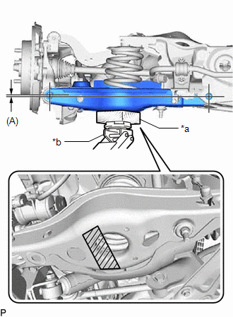
| *a | Wooden Block |
| *b | Jack |
.png) | Jack Point |
Standard Length (A):
4.4 mm (0.1732 in.)
NOTICE:
Do not jack up the rear No. 2 suspension arm assembly too high as the vehicle may fall.
HINT:
- If the rear No. 2 suspension arm assembly cannot be positioned as shown in the illustration even when the rear No. 2 suspension arm assembly is jacked up, apply additional load by placing a weight in the luggage compartment.
- Use the same procedure for the RH and LH sides.
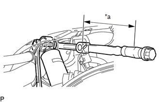
4. TIGHTEN REAR SHOCK ABSORBER ASSEMBLY LH
| (a) Using 17 mm ball joint lock nut wrench, tighten the nut on the rear shock absorber LH (upper side). Torque: Specified tightening torque : 83 N·m {846 kgf·cm, 61 ft·lbf} NOTICE: Since a stopper bolt is used, tighten the nut. HINT:
|
|
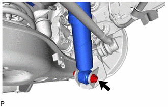
| (b) Tighten the bolt on the rear shock absorber (lower side). Torque: 83 N·m {846 kgf·cm, 61 ft·lbf} |
|
5. INSTALL REAR SUSPENSION ARM COVER LH
Click here .gif)
6. CONNECT REAR SPEED SENSOR LH
(a) w/ AVS:
Click here
(b) w/o AVS:
Click here
7. INSTALL REAR WHEEL
Click here
8. INSPECT AND ADJUST REAR WHEEL ALIGNMENT
Click here
9. CHECK FOR SPEED SENSOR SIGNAL
Click here
10. PERFORM INITIALIZATION
Click here
READ NEXT:
 Disposal
DISPOSAL PROCEDURE 1. DISPOSE OF REAR SHOCK ABSORBER ASSEMBLY LH *A w/o AVS *B w/ AVS (a) Extend the piston rod and secure the rear shock absorber assembly at an angle in a vise. (b) Us
Components
COMPONENTS ILLUSTRATION *1 REAR NO. 1 STABILIZER BAR BRACKET *2 REAR STABILIZER BAR *3 REAR STABILIZER BUSHING *4 REAR STABILIZER LINK ASSEMBLY LH *5 REAR STABILIZER LINK ASS
SEE MORE:
Components
COMPONENTS ILLUSTRATION *1 NO. 1 AIR DUCT *2 QUICK HEATER ASSEMBLY ● Non-reusable part - -
High Voltage Fuse (P0A95-400)
DESCRIPTION The hybrid vehicle control ECU estimates the thermal load of the high voltage fuse. If the accumulated thermal load exceeds the threshold, the hybrid vehicle control ECU will store this DTC. DTC No. Detection Item DTC Detection Condition Trouble Area MIL Warning Indicate
