Lexus NX: Installation
INSTALLATION
PROCEDURE
1. INSTALL MULTIPLEX NETWORK BODY ECU (MAIN BODY ECU)
NOTICE:
- Make sure that no foreign matter gets on the connecting surfaces.
- Do not touch the ECU connector.
(a) Insert the multiplex network body ECU (main body ECU) up to the position where it contacts the housing sidewall of the guide as shown in the illustration.
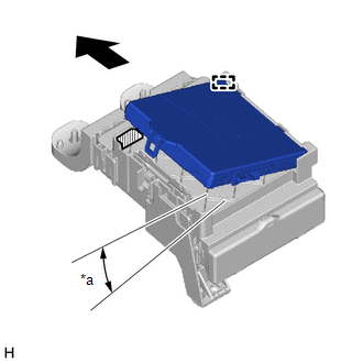
| *a | 20° |
.png) | Housing Sidewall |
HINT:
Make sure to keep the angle 20° or more as shown in the illustration.
(b) Slide the multiplex network body ECU (main body ECU) along the housing sidewall so that it attaches to the 2 guides.
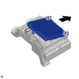
.png) | Slide |
| | Housing Sidewall |
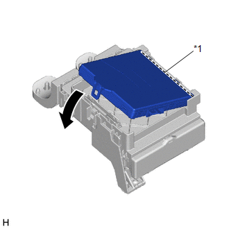
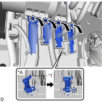
| (c) While keeping the multiplex network body ECU (main body ECU) in contact with side A of the junction block (axis of rotation), rotate it downward as shown in the illustration. |
|
(d) Press the push area until the claw engages to install the multiplex network body ECU (main body ECU).
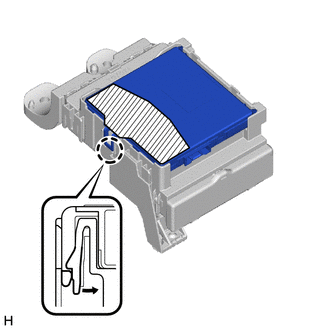
| | Push Area |
NOTICE:
- Make sure to press only the push area.
- Confirm the engagement of the multiplex network body ECU (main body ECU) and junction block by listening for the lock sound.
HINT:
If a lock sound cannot be heard, visually check the lock part engagement. The engagement can also be confirmed if the multiplex network body ECU (main body ECU) and junction block are flush.
2. INSTALL INSTRUMENT PANEL JUNCTION BLOCK ASSEMBLY
(a) Connect the 3 connectors to the multiplex network body ECU (main body ECU).
(b) Install the instrument panel junction block assembly with the bolt and 2 nuts.
Torque:
for Bolt :
8.4 N·m {86 kgf·cm, 74 in·lbf}
for Nut :
8.4 N·m {86 kgf·cm, 74 in·lbf}
(c) Connect the lower side of the instrument panel junction block assembly connector.
| (d) w/o Connector Stopper: (1) Connect the connector and lock the connector lock lever. HINT: Use the same procedure to connect the remaining 3 connectors. |
|
(e) w/ Connector Stopper:
(1) Connect the connector and lock the connector lock lever.
HINT:
Use the same procedure to connect the remaining 3 connectors.
(2) Attach the claw to lock the connector stopper.
(f) Attach the 2 wire harness clamps.
(g) Attach the claw to connect the connector housing.
(h) Connect the connector.
3. INSTALL LOWER NO. 1 INSTRUMENT PANEL FINISH PANEL
Click here .gif)
4. INSTALL NO. 1 INSTRUMENT PANEL UNDER COVER SUB-ASSEMBLY
Click here
5. INSTALL UPPER NO. 2 CONSOLE PANEL GARNISH
Click here
6. INSTALL REAR CONSOLE ARMREST ASSEMBLY
Click here
7. INSTALL NO. 1 INSTRUMENT PANEL SAFETY PAD SUB-ASSEMBLY
Click here
8. INSTALL INSTRUMENT SIDE PANEL LH
Click here
9. INSTALL COWL SIDE TRIM BOARD LH
Click here
10. INSTALL DOOR SCUFF PLATE ASSEMBLY LH
Click here
11. CONNECT CABLE TO NEGATIVE AUXILIARY BATTERY TERMINAL
(a) Connect the negative (-) auxiliary battery terminal and tighten the nut.
Torque:
5.4 N·m {55 kgf·cm, 48 in·lbf}
12. INITIALIZATION AFTER RECONNECTING AUXILIARY BATTERY TERMINAL
Click here
HINT:
When disconnecting and reconnecting the auxiliary battery, there is an automatic learning function that completes learning when the respective system is used.
Click here
13. INSTALL DECK FLOOR BOX LH
Click here
14. INSTALL REAR DECK FLOOR BOX
Click here
15. INSTALL NO. 3 DECK BOARD SUB-ASSEMBLY
Click here
16. PERFORM REGISTRATION
Click here
READ NEXT:
 Power Steering Ecu (for Manual Tilt And Manual Telescopic Steering Column)
ComponentsCOMPONENTS ILLUSTRATION *1 ELECTRIC POWER STEERING COLUMN SUB-ASSEMBLY *2 POWER STEERING ECU ASSEMBLY *3 POWER STEERING ECU PROTECTOR *4 ECU WIRE SUB-ASSEMBLY N*m
SEE MORE:
Stereo Component Amplifier Malfunction (B15A3)
DESCRIPTION These DTCs are stored when a malfunction occurs in the stereo component amplifier assembly. DTC No. Detection Item DTC Detection Condition Trouble Area B15A3 Stereo Component Amplifier Malfunction When one of the conditions below is met:
Internal power supply malfunct
Removal
REMOVAL CAUTION / NOTICE / HINT HINT:
Use the same procedure for the RH and LH sides.
The procedure listed below is for the LH side.
PROCEDURE 1. PRECAUTION NOTICE: After the power switch off is turned off, there may be a waiting time before disconnecting the auxiliary negative (-) battery t
