Lexus NX: Power Steering Ecu (for Manual Tilt And Manual Telescopic Steering Column)
Components
COMPONENTS
ILLUSTRATION
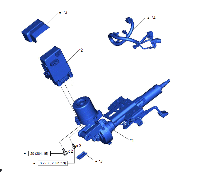
| *1 | ELECTRIC POWER STEERING COLUMN SUB-ASSEMBLY | *2 | POWER STEERING ECU ASSEMBLY |
| *3 | POWER STEERING ECU PROTECTOR | *4 | ECU WIRE SUB-ASSEMBLY |
 | N*m (kgf*cm, ft.*lbf): Specified torque | ● | Non-reusable part |
Removal
REMOVAL
CAUTION / NOTICE / HINT
PROCEDURE
1. REMOVE ELECTRIC POWER STEERING COLUMN SUB-ASSEMBLY
Click here 
2. REMOVE POWER STEERING ECU ASSEMBLY
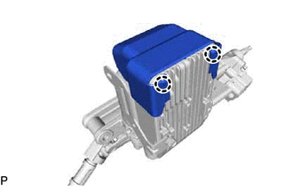
| (a) Detach the 2 claws and remove the power steering ECU protector from the power steering ECU assembly. |
|
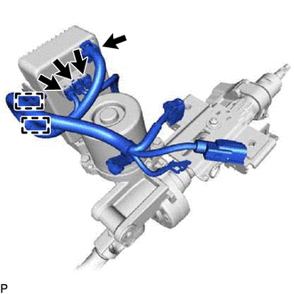
| (b) Disconnect the connectors and 2 harness clamps, and remove the ECU wire sub-assembly from the power steering ECU assembly. |
|
| (c) Detach the 4 claws and remove the power steering ECU protector from the power steering ECU assembly. |
|
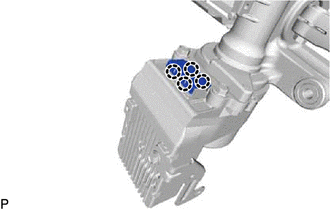
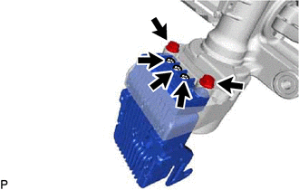
| (d) Remove the 3 terminal bolts, 2 bolts and power steering ECU assembly from the electric power steering column sub-assembly. |
|
Installation
INSTALLATION
CAUTION / NOTICE / HINT
PROCEDURE
1. INSTALL POWER STEERING ECU ASSEMBLY
(a) Install the power steering ECU assembly with 2 new bolts.
Torque:
20 N·m {204 kgf·cm, 15 ft·lbf}
(b) Install 3 new terminal bolts.
Torque:
3.2 N·m {33 kgf·cm, 28 in·lbf}
(c) Connect the connectors and 2 harness clamps, and install a new ECU wire sub-assembly to the power steering ECU assembly.
(d) Install 2 new power steering ECU protectors to the power steering ECU assembly.
2. INSTALL ELECTRIC POWER STEERING COLUMN SUB-ASSEMBLY
Click here .gif)
3. PERFORM ASSIST MAP WRITING
Click here
READ NEXT:
 Components
COMPONENTS ILLUSTRATION *1 ELECTRIC POWER STEERING COLUMN SUB-ASSEMBLY *2 POWER STEERING ECU ASSEMBLY *3 POWER STEERING ECU PROTECTOR *4 ECU WIRE SUB-ASSEMBLY *5 ELECTRIC POW
Removal
REMOVAL CAUTION / NOTICE / HINT PROCEDURE 1. REMOVE ELECTRIC POWER STEERING COLUMN SUB-ASSEMBLY Click here 2. REMOVE POWER STEERING ECU ASSEMBLY (a) Detach the claw and remove the power steering
SEE MORE:
Removal
REMOVAL PROCEDURE 1. REMOVE DOOR SCUFF PLATE ASSEMBLY LH Click here 2. REMOVE COWL SIDE TRIM BOARD LH Click here 3. REMOVE NO. 1 INSTRUMENT PANEL UNDER COVER SUB-ASSEMBLY Click here 4. REMOVE STOP LIGHT SWITCH ASSEMBLY (a) Disconnect the connector. (b) Loosen the lock
Speaker Circuit
DESCRIPTION If there is a short in a speaker circuit, the stereo component amplifier assembly detects it and stops output to the speakers. As a result, sound cannot be heard from the speakers even if there is no malfunction in the stereo component amplifier assembly, DCM (telematics transceiver)* or
