Lexus NX: Components
COMPONENTS
ILLUSTRATION
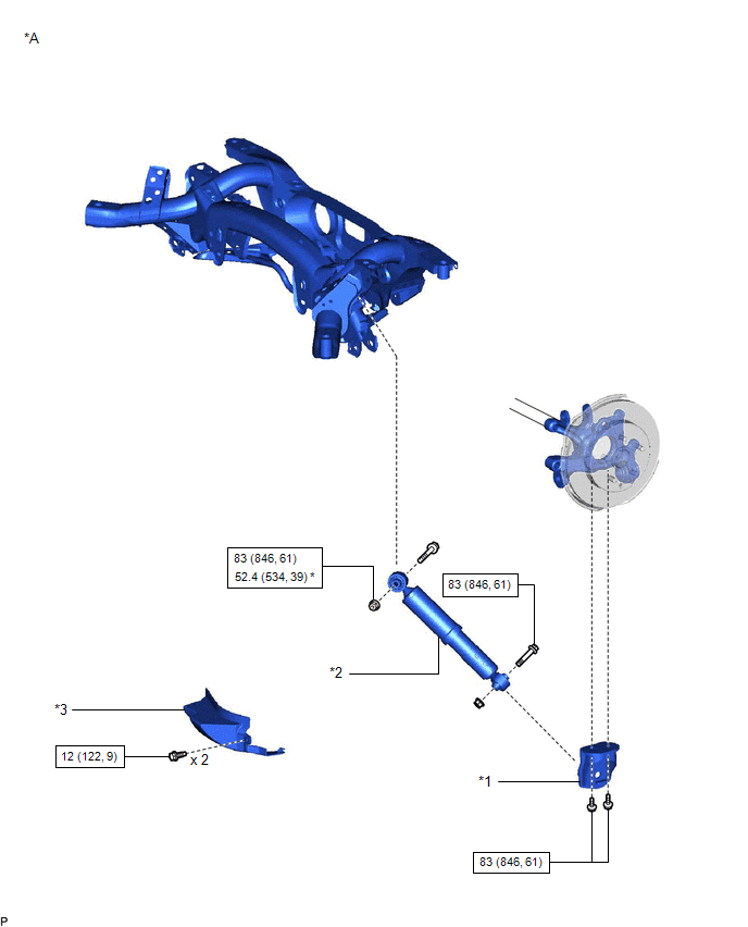
| *A | w/o AVS | - | - |
| *1 | REAR NO. 1 SHOCK ABSORBER BRACKET LH | *2 | REAR SHOCK ABSORBER ASSEMBLY LH |
| *3 | REAR SUSPENSION ARM COVER LH | - | |
.png) | N*m (kgf*cm, ft.*lbf): Specified torque | * | For use with ball joint lock nut wrench |
ILLUSTRATION

| *A | w/ AVS | - | - |
| *1 | REAR NO. 1 SHOCK ABSORBER BRACKET LH | *2 | REAR SHOCK ABSORBER ASSEMBLY LH |
| *3 | REAR SUSPENSION ARM COVER LH | - | - |
| | N*m (kgf*cm, ft.*lbf): Specified torque | * | For use with ball joint lock nut wrench |
READ NEXT:
 Removal
REMOVAL CAUTION / NOTICE / HINT HINT:
Use the same procedure for the RH and LH sides.
The procedure listed below is for the LH side.
PROCEDURE 1. REMOVE REAR WHEEL Click here 2. DISCONNECT R
Inspection
INSPECTION PROCEDURE 1. INSPECT REAR SHOCK ABSORBER ASSEMBLY LH (a) Compress and extend the shock absorber rod and check that there is no abnormal resistance or unusual sound during operation. If ther
Installation
INSTALLATION CAUTION / NOTICE / HINT HINT:
Use the same procedure for the RH and LH sides.
The procedure listed below is for the LH side.
PROCEDURE 1. TEMPORARILY INSTALL REAR NO. 1 SHOCK ABSO
SEE MORE:
Dcm(telematics Transceiver)
ComponentsCOMPONENTS ILLUSTRATION *1 DECK FLOOR BOX LH *2 NO. 3 DECK BOARD SUB-ASSEMBLY *3 REAR DECK FLOOR BOX *4 NEGATIVE AUXILIARY BATTERY TERMINAL N*m (kgf*cm, ft.*lbf): Specified torque - - ILLUSTRATION *A for 8 Inch *B for 10.3 Inch *1 AIR COND
Customize Parameters
CUSTOMIZE PARAMETERS CUSTOMIZE SEAT BELT WARNING SYSTEM HINT: The following items can be customized. NOTICE:
When the customer requests a change in a function, first make sure that the function can be customized.
Record the current settings before customizing.
(a) Customizing with the Techst
© 2016-2026 Copyright www.lexunx.com
