Lexus NX: Installation
INSTALLATION
CAUTION / NOTICE / HINT
HINT:
- Use the same procedure for the RH and LH sides.
- The procedure listed below is for the LH side.
PROCEDURE
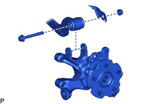
1. TEMPORARILY INSTALL REAR UPPER CONTROL ARM ASSEMBLY LH
| (a) Temporarily install the rear upper control arm to the rear suspension member with the bolt and nut. |
|
.png)
| (b) Temporarily install the rear upper control arm to the rear axle carrier with the bolt, parking brake wire bracket and nut. NOTICE:
|
|
2. STABILIZE SUSPENSION
Click here .gif)
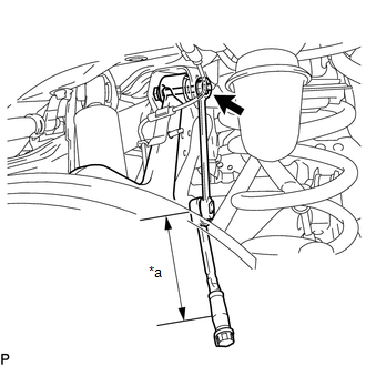
3. TIGHTEN REAR UPPER CONTROL ARM ASSEMBLY LH
| (a) Tighten the bolt of the upper control arm. Torque: 90 N·m {918 kgf·cm, 66 ft·lbf} |
|
.png)
| (b) Using a 19 mm ball joint lock nut wrench, tighten the bolt on the rear upper control arm assembly LH. Torque: Specified tightening torque : 90 N·m {918 kgf·cm, 66 ft·lbf} HINT:
|
|
4. CONNECT PARKING BRAKE WIRE ASSEMBLY NO.1
Click here
5. CONNECT REAR SPEED SENSOR LH
(a) w/ AVS:
Click here
(b) w/o AVS:
Click here
6. INSTALL REAR SUSPENSION ARM COVER LH
Click here
7. INSTALL REAR WHEEL
Click here
8. INSPECT AND ADJUST REAR WHEEL ALIGNMENT
Click here
9. PERFORM INITIALIZATION
Click here
READ NEXT:
 Absorber Control Actuator (for Front Side)
On-vehicle InspectionON-VEHICLE INSPECTION PROCEDURE 1. INSPECT ABSORBER CONTROL ACTUATOR (a) Measure the resistance according to the value(s) in the table below. Standard Resistance: for LH Side
Absorber Control Actuator (for Rear Side)
On-vehicle InspectionON-VEHICLE INSPECTION PROCEDURE 1. INSPECT ABSORBER CONTROL ACTUATOR (a) Measure the resistance according to the value(s) in the table below. Standard Resistance: for LH Side
SEE MORE:
How To Proceed With Troubleshooting
CAUTION / NOTICE / HINT HINT:
Use the following procedure to troubleshoot the power door lock control system.
*: Use the Techstream.
PROCEDURE 1. VEHICLE BROUGHT TO WORKSHOP
NEXT 2. CUSTOMER PROBLEM ANALYSIS CHECK HINT:
In troubleshooting, confirm that t
System Diagram
SYSTEM DIAGRAM SYSTEM DIAGRAM (a) The CAN communication system is composed of 5 buses. CAN Main Bus Line Terminating Resistor CAN Branch Line * Gateway Function Equipped ECU Bus Monitoring Direction - - Connected to Code ECU/Sensor Name CAN DTC Storage
