Lexus NX: Installation
INSTALLATION
PROCEDURE
1. INSTALL MULTIPLEX NETWORK DOOR ECU
(a) Connect the 2 connectors.
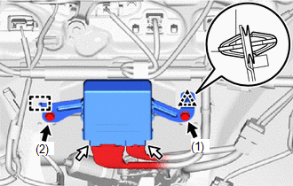
.png) | Bolt |
.png) | Connector |
(b) Attach the guide and clip to install the multiplex network door ECU.
NOTICE:
Be careful not to drop the multiplex network door ECU as it may become damaged.
(c) Install the 2 bolts in the order shown in the illustration.
Torque:
8.4 N·m {86 kgf·cm, 74 in·lbf}
2. INSTALL BACK DOOR TRIM BOARD ASSEMBLY
Click here .gif)
3. INSTALL BACK DOOR LOCK COVER
Click here
4. INSTALL PULL HANDLE
Click here
5. INSTALL BACK DOOR TRIM BASE
Click here
6. INSTALL BACK DOOR SIDE GARNISH LH
Click here
7. INSTALL BACK DOOR SIDE GARNISH RH
Click here
8. INSTALL BACK DOOR CENTER GARNISH
Click here
9. INSPECT POWER BACK DOOR SYSTEM
Click here
READ NEXT:
 Parts Location
PARTS LOCATION ILLUSTRATION *1 BACK DOOR OPENER SWITCH ASSEMBLY *2 MULTIPLEX NETWORK DOOR ECU *3 BACK DOOR LOCK ASSEMBLY *4 BACK DOOR LOCK MOTOR *5 LATCH SWITCH *6 PAWL S
System Diagram
SYSTEM DIAGRAM Communication Table Transmitting ECU Receiver ECU Signal Communication Method Certification ECU (Smart Key ECU Assembly) Main Body ECU (Multiplex Network Body ECU) Bac
SEE MORE:
High Beam Headlight Circuit
DESCRIPTION The main body ECU (multiplex network body ECU) controls the high beam headlights. WIRING DIAGRAM CAUTION / NOTICE / HINT NOTICE:
Inspect the fuses for circuits related to this system before performing the following procedure.
Recognition code registration is necessary when replacin
Installation
INSTALLATION CAUTION / NOTICE / HINT HINT:
Use the same procedure for the RH and LH sides.
The procedure listed below is for the LH side.
PROCEDURE 1. INSTALL SIDE TELEVISION CAMERA ASSEMBLY LH (a) Install the side television camera assembly LH with the 2 screws. 2. INSTALL LOWER OUTER MIRRO
© 2016-2026 Copyright www.lexunx.com
