Lexus NX: Parts Location
Lexus NX Service Manual / Vehicle Exterior / Door / Hatch / Back Door Closer System / Parts Location
PARTS LOCATION
ILLUSTRATION
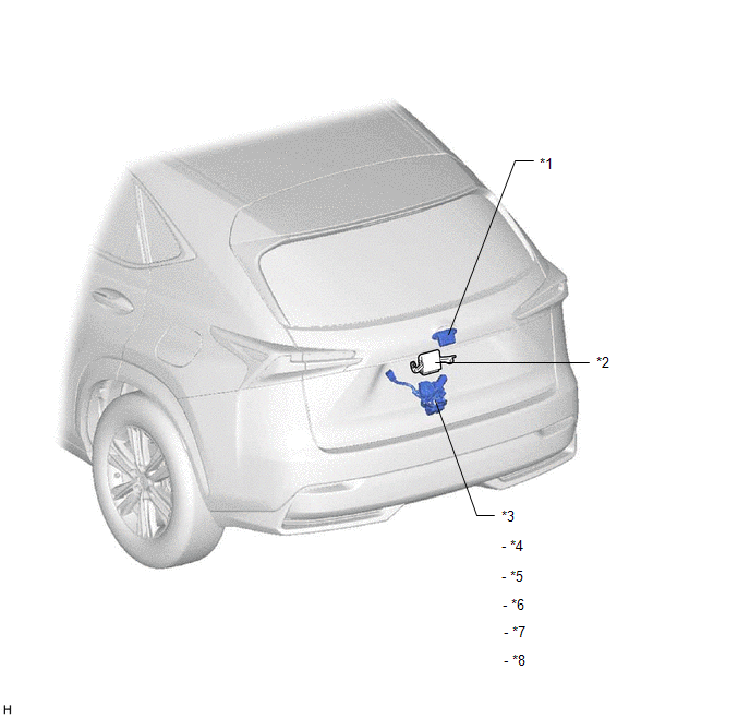
| *1 | BACK DOOR OPENER SWITCH ASSEMBLY | *2 | MULTIPLEX NETWORK DOOR ECU |
| *3 | BACK DOOR LOCK ASSEMBLY | *4 | BACK DOOR LOCK MOTOR |
| *5 | LATCH SWITCH | *6 | PAWL SWITCH |
| *7 | BACK DOOR COURTESY SWITCH | *8 | INITIAL SWITCH |
ILLUSTRATION
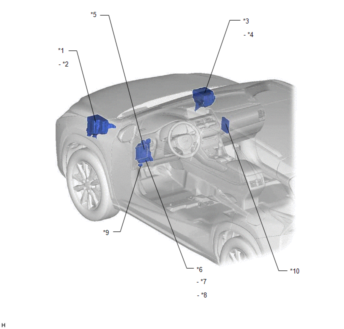
| *1 | ENGINE ROOM RELAY BLOCK | *2 | AM2 FUSE |
| *3 | NO. 2 ENGINE ROOM RELAY BLOCK | *4 | ECU-B NO.1 FUSE |
| *5 | MAIN BODY ECU (MULTIPLEX NETWORK BODY ECU) | *6 | INSTRUMENT PANEL JUNCTION BLOCK ASSEMBLY |
| *7 | PBD FUSE | *8 | ECU-IG NO.1 FUSE |
| *9 | DLC3 | *10 | CERTIFICATION ECU (SMART KEY ECU ASSEMBLY) |
READ NEXT:
 System Diagram
SYSTEM DIAGRAM Communication Table Transmitting ECU Receiver ECU Signal Communication Method Certification ECU (Smart Key ECU Assembly) Main Body ECU (Multiplex Network Body ECU) Bac
System Description
SYSTEM DESCRIPTION BACK DOOR CLOSER SYSTEM DESCRIPTION (a) Operating any back door opener switch assembly when the back door is fully closed inputs a request signal to the multiplex network door ECU.
How To Proceed With Troubleshooting
CAUTION / NOTICE / HINT HINT:
The back door closer system troubleshooting procedure is based on the premise that the power back door system is operating normally. Check the power back door system f
SEE MORE:
Dtc Check / Clear
DTC CHECK / CLEAR NOTICE: When using the Techstream with the power switch off, connect the Techstream to the DLC3 and turn a courtesy light switch on and off at intervals of 1.5 seconds or less until communication between the Techstream and the vehicle begins. Then select the vehicle type under manu
Diagnostic Trouble Code Chart
DIAGNOSTIC TROUBLE CODE CHART Sliding Roof System DTC No. Detection Item Link B2341 Sensor (Motor) Failure B2342 Switch Failure B2343 Position Initialization Incomplete B2344 Position Failure
© 2016-2026 Copyright www.lexunx.com
