Lexus NX: Removal
REMOVAL
CAUTION / NOTICE / HINT
HINT:
When the front bumper is damaged or deformed due to an accident or contact with other objects, etc., or the bumper installation area on the body is repaired, it is necessary to perform millimeter wave radar sensor adjustment (See page .gif) ).
).
PROCEDURE
1. PRECAUTION (w/ Panoramic View Monitor System)
Click here
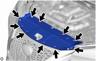
2. REMOVE RADIATOR SUPPORT OPENING COVER
| (a) Remove the 10 clips and radiator support opening cover. |
|
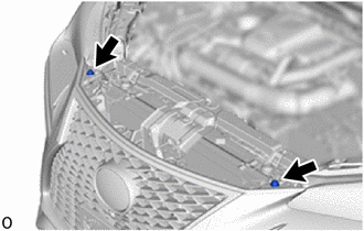
3. REMOVE RADIATOR GRILLE PROTECTOR
| (a) Remove the 2 radiator grille protectors. |
|
4. REMOVE FRONT FENDER MOULDING SUB-ASSEMBLY LH (for Front Fender)
Click here
5. REMOVE FRONT FENDER MOULDING SUB-ASSEMBLY RH (for Front Fender)
HINT:
Use the same procedure described for the LH side.
6. REMOVE NO. 1 MOULDING TAPE (for Front Fender)
Click here
7. REMOVE NO. 2 MOULDING TAPE (for Front Fender)
Click here
8. REMOVE FRONT FENDER FRONT SPLASH SHIELD LH
| (a) Remove the 5 screws and front fender front splash shield LH. |
|
9. REMOVE FRONT FENDER FRONT SPLASH SHIELD RH
HINT:
Use the same procedure described for the LH side.
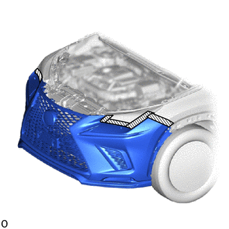
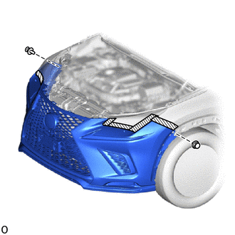
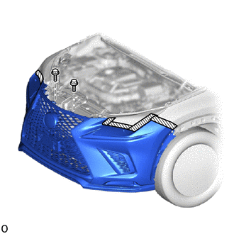
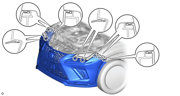
10. REMOVE FRONT BUMPER ASSEMBLY
| (a) Remove the 6 screws. |
|
(b) Put protective tape around the front bumper assembly.
.png) | Protective Tape |
| (c) Remove the 2 clips. |
|
| (d) Remove the 2 bolts. |
|
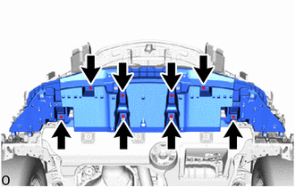
(e) Detach the 10 claws and remove the front bumper assembly.
(f) w/ Headlight Cleaner System:
(1) Disconnect the headlight washer hose, and then drain the washer fluid.
HINT:
Use a container to collect the washer fluid.
(g) Disconnect the 2 fog light connectors.
(h) Disconnect the 2 clearance light connectors.
(i) w/ Intuitive Parking Assist System:
Disconnect the 2 No. 3 engine room wire connectors.
(j) w/o Intuitive Parking Assist System:
Disconnect the No. 3 engine room wire connector.
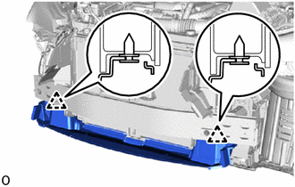
11. REMOVE FRONT BUMPER ENERGY ABSORBER
Click here
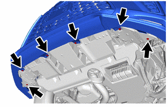
12. REMOVE FRONT BUMPER LOWER ABSORBER
| (a) Remove the 8 screws and front bumper lower absorber. |
|
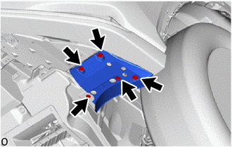
13. REMOVE LOWER RADIATOR AIR GUIDE PLATE
| (a) Detach the 2 clips and remove the lower radiator air guide plate. |
|
14. REMOVE FRONT BUMPER SIDE MOUNTING BRACKET ASSEMBLY LH
Click here
15. REMOVE FRONT BUMPER REINFORCEMENT SUB-ASSEMBLY
Click here
16. REMOVE FRONT BUMPER SIDE RETAINER LH
Click here
17. REMOVE FRONT BUMPER SIDE RETAINER RH
HINT:
Use the same procedure described for the LH side.
READ NEXT:
 Disassembly
DISASSEMBLY PROCEDURE 1. REMOVE HEADLIGHT WASHER ACTUATOR SUB-ASSEMBLY RH (w/ Headlight Cleaner System) Click here 2. REMOVE HEADLIGHT WASHER ACTUATOR SUB-ASSEMBLY LH (w/ Headlight Cleaner System) H
Reassembly
REASSEMBLY PROCEDURE 1. INSTALL NO. 2 MOULDING TAPE HINT:
When installing the No. 2 moulding tape, heat the front bumper cover and No. 2 moulding tape using a heat light.
Use the same procedure d
Installation
INSTALLATION CAUTION / NOTICE / HINT HINT: A bolt without a torque specification is shown in the standard bolt chart. Click here PROCEDURE 1. INSTALL FRONT BUMPER SIDE RETAINER LH Click here 2. IN
SEE MORE:
Trouble in Passenger Airbag ON/OFF Indicator
DESCRIPTION The occupant classification system detects the front passenger seat condition. It then displays the front passenger airbag condition (activated/not activated) using the passenger airbag ON/OFF indicator. HINT: Approximately 6 seconds after the power switch is turned on (IG), the passenge
Vehicle Identification Malfunction (C1789)
DESCRIPTION
When the absorber control ECU has not acquired the vehicle identification information, DTC C1789 is stored. When the vehicle identification information is correctly acquired, this DTC is cleared. Vehicle identification information is automatically acquired when the system enters test
