Lexus NX: Installation
INSTALLATION
PROCEDURE
1. INSTALL HEATER ACCESSORY ASSEMBLY
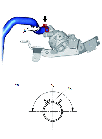
| (a) Connect the heater water inlet hose A with the paint mark (Blue) facing up and attach the clip within the area shown in the illustration. NOTICE: Do not apply excessive force to the heater water inlet hose A. |
|
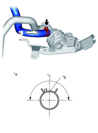
| (b) Connect the heater water outlet hose A with the indentation part facing up and attach the clip within the area shown in the illustration. NOTICE: Do not apply excessive force to the heater water outlet hose A. |
|
| (c) Temporarily install the heater water pump assembly (heater water pump) with the 3 bolts and nut. |
|
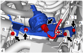
(d) Tighten the 3 bolts and nut in the order as shown in the illustration.
Torque:
Bolt A, Nut A :
9.8 N·m {100 kgf·cm, 87 in·lbf}
Bolt B :
7.7 N·m {79 kgf·cm, 68 in·lbf}
(e) Attach the clamp.
(f) Connect the connector.
2. INSTALL AIR CLEANER CASE SUB-ASSEMBLY
Click here .gif)
3. INSTALL AIR CLEANER FILTER ELEMENT SUB-ASSEMBLY
Click here
4. INSTALL AIR CLEANER CAP SUB-ASSEMBLY
Click here
5. ADD ENGINE COOLANT (for Inverter Coolant)
Click here
6. INSPECT FOR COOLANT LEAK (for Inverter Coolant)
Click here
READ NEXT:
 Components
COMPONENTS ILLUSTRATION *1 AIR CONDITIONING THERMISTOR ASSEMBLY (HUMIDITY SENSOR) *2 NO. 1 FORWARD RECOGNITION COVER *3 NO. 2 FORWARD RECOGNITION COVER *4 PROTECTOR
Removal
REMOVAL PROCEDURE 1. REMOVE NO. 2 FORWARD RECOGNITION COVER Click here 2. REMOVE NO. 1 FORWARD RECOGNITION COVER Click here 3. REMOVE PROTECTOR (a) Detach the 2 claws and remove the protector.
SEE MORE:
Parts Location
PARTS LOCATION ILLUSTRATION *1 NO. 2 ENGINE ROOM RELAY BLOCK - DCM FUSE *2 TELEPHONE AND GPS ANTENNA (ROOF ANTENNA ASSEMBLY) ILLUSTRATION *1 TELEPHONE ANTENNA (NAVIGATION ANTENNA ASSEMBLY) *2 COMBINATION METER ASSEMBLY *3 MULTI-DISPLAY ASSEMBLY *4 DCM (TELEMATICS TRA
Installation
INSTALLATION PROCEDURE 1. INSTALL EXHAUST PIPE DAMPER (a) Install the exhaust pipe damper with the 2 bolts. Torque: 19 N·m {194 kgf·cm, 14 ft·lbf} 2. INSTALL HEATED OXYGEN SENSOR Click here 3. INSTALL FRONT EXHAUST PIPE ASSEMBLY (a) Using a vernier caliper, measure the free length of the co
