Lexus NX: Installation
INSTALLATION
CAUTION / NOTICE / HINT
HINT:
- Use the same procedure for the RH and LH sides.
- The procedure listed below is for the LH side.
PROCEDURE
1. INSTALL SIDE MUDGUARD SUB-ASSEMBLY LH
HINT:
When installing the side mudguard sub-assembly LH, heat the vehicle body and side mudguard sub-assembly LH using a heat light.
Standard:
| Item | Temperature |
|---|---|
| Vehicle Body | 40 to 60°C (104 to 140°F) |
| Side Mudguard Sub-assembly LH | 20 to 30°C (68 to 86°F) |
NOTICE:
Do not heat the vehicle body or side mudguard sub-assembly LH excessively.
(a) Clean the vehicle body surface.
(1) Using a heat light, heat the vehicle body surface.
(2) Remove the double-sided tape from the back door panel.
(3) Wipe off any tape adhesive residue with cleaner.
(b) Install the side mudguard sub-assembly LH.
(1) Using a heat light, heat the vehicle body.
(2) Remove the peeling paper from the face of the No. 3 moulding tape.
HINT:
After removing the peeling paper, keep the exposed adhesive free from foreign matter.
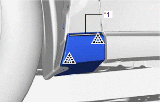
| (3) Attach the 2 clips so as to apply the No. 3 moulding tape and install the side mudguard sub-assembly LH as shown in the illustration. HINT: Press the side mudguard sub-assembly LH firmly to install it. |
|
(c) Install a new grommet.
(d) Install the clip.
(e) Install the screw.
READ NEXT:
 Components
COMPONENTS ILLUSTRATION *1 FRONT FENDER MOULDING SUB-ASSEMBLY LH - - ILLUSTRATION *1 NO. 1 MOULDING TAPE *2 NO. 2 MOULDING TAPE ● Non-reusable part - -
Removal
REMOVAL CAUTION / NOTICE / HINT HINT:
Use the same procedure for the RH and LH sides.
The procedure listed below is for the LH side.
PROCEDURE 1. REMOVE FRONT FENDER MOULDING SUB-ASSEMBLY LH H
SEE MORE:
BSM (Blind Spot Monitor)
The Blind Spot Monitor uses the
sensors installed behind the rear
bumper. The system is intended to
assist the driver check areas that
are not easily visible. The system
has the following 2 functions:
The Blind Spot Monitor function
Assists the driver in making the decision
when changin
Terminals Of Ecu
TERMINALS OF ECU CHECK CERTIFICATION ECU (SMART KEY ECU ASSEMBLY) (a) Disconnect the I51 and I53 certification ECU (smart key ECU assembly) connectors. (b) Measure the voltage and resistance according to the value(s) in the table below. HINT: Measure the values on the wire harness side with the con
