Lexus NX: Installation
INSTALLATION
PROCEDURE
1. INSTALL STOP LIGHT SWITCH ASSEMBLY
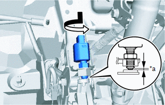
| (a) Turn the stop light switch assembly in the clockwise direction until it reaches the standard shaft protrusion amount and temporarily install it. Standard: 0.5 to 1.7 mm (0.0197 to 0.0669 in.) NOTICE: Do not depress the brake pedal. |
|
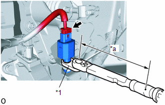
| (b) Using a union nut wrench and a torque wrench, tighten the lock nut. Torque: Specified tightening torque 16.7 N*m (170 kgf*cm, 12 ft.*lbf) HINT:
|
|
(c) Connect the connector.
2. INSTALL NO. 1 INSTRUMENT PANEL UNDER COVER SUB-ASSEMBLY
Click here .gif)
3. INSTALL COWL SIDE TRIM BOARD LH
Click here
4. INSTALL DOOR SCUFF PLATE ASSEMBLY LH
Click here
5. INSPECT STOP LIGHT
(a) Depress the brake pedal and check that the brake light illuminates.
READ NEXT:
 Components
COMPONENTS ILLUSTRATION *A for Driver Side *B for Front Passenger Side *1 FRONT DOOR INSIDE HANDLE BEZEL PLUG LH *2 FRONT DOOR TRIM BOARD SUB-ASSEMBLY LH *3 FRONT DOOR TRIM C
SEE MORE:
Steering Vibrator Component Internal Failure (C1A7496)
DESCRIPTION If the forward recognition camera receives a steering vibration ECU malfunction signal, DTC C1A7496 is stored. DTC No. Detection Item DTC Detection Condition Trouble Area C1A7496 Steering Vibrator Component Internal Failure 3 seconds after the power switch is turned on (
Back Door Courtesy Switch Circuit
DESCRIPTION The fold seat control ECU receives the switch operation signal, driving condition signal and back door open/close signal from the back door lock assembly. The fold seat control ECU actives the rear seat according to these signals. WIRING DIAGRAM PROCEDURE 1. CHECK BACK DOOR LOCK A
