Lexus NX: Installation
INSTALLATION
CAUTION / NOTICE / HINT
HINT:
- Use the same procedure for the RH and LH sides.
- The procedure listed below is for the LH side.
-
A bolt without a torque specification is shown in the standard bolt chart.
Click here
.gif)
PROCEDURE
1. CLEAN QUARTER WINDOW ASSEMBLY LH
| (a) Clean the outer edge of a new quarter window assembly LH with non-residue solvent. NOTICE:
|
|
.png)
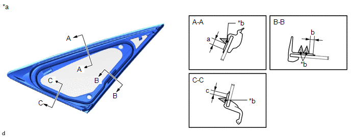
2. INSTALL QUARTER WINDOW ASSEMBLY LH
| *1 | Vehicle Body |
.png) | Adhesive |
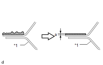
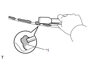
(a) Clean and shape the contact surface of the vehicle body.
(1) On the contact surface of the vehicle body, use a knife to cut away excess adhesive as shown in the illustration.
HINT:
Leave as much adhesive on the vehicle body as possible.
Standard:
| Area | Specified Condition |
|---|---|
| a | 1.0 mm (0.0394 in.) |
NOTICE:
Be careful not to damage the vehicle body.
(2) Clean the contact surface of the vehicle body with cleaner.
HINT:
Even if all the adhesive has been removed, clean the vehicle body.
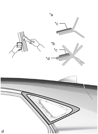
| *a | CORRECT |
| *b | INCORRECT |
| *c | Primer M |
| *d | Adhesive |
| | Primer M Application Area |
(b) Using a brush or sponge, apply Primer M to the exposed part of the vehicle body.
NOTICE:
- Allow the Primer M coating to dry for 3 minutes or more.
- Throw away any leftover primer.
- Do not apply too much primer.
(c) Using a brush or sponge, apply Primer G to the contact surface of a new quarter window assembly LH.
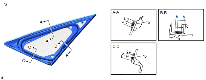
| *a | Back Side | *b | Adhesive Center Line |
| | Primer G Application Area | - | - |
Standard:
| Area | Specified Condition |
|---|---|
| a | 6.0 mm (0.2362 in.) or more |
| b | 3.0 mm (0.1181 in.) |
| c | 3.0 mm (0.1181 in.) or more |
HINT:
If primer is applied to an area that is not specified, wipe off the primer with non-residue solvent before it dries.
NOTICE:
- Allow the primer to dry for 3 minutes or more.
- Throw away any leftover primer.
- Do not apply too much primer.
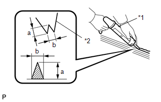
| (d) Cut off the tip of the cartridge nozzle as shown in the illustration. Standard:
HINT: After cutting off the tip, use all adhesive within the time written in the table below. Usage Time Frame:
|
|
(e) Load the sealer gun with the cartridge.
(f) Apply adhesive to the quarter window assembly LH.
Adhesive:
Toyota Genuine Windshield Glass Adhesive or Equivalent
(1) Apply adhesive to the quarter window assembly LH as shown in the illustration.
| *a | Back Side | *b | Adhesive Center Line |
Standard:
| Area | Specified Condition |
|---|---|
| a | 3.0 mm (0.1181 in.) or more |
| b | 3.0 mm (0.1181 in.) or more |
| c | 3.0 mm (0.1181 in.) or more |
(g) Install the quarter window assembly LH to the vehicle body.
(1) Hold the quarter window assembly LH in place securely with protective tape or equivalent until the adhesive hardens.
NOTICE:
- Allow the primer coating to dry for 3 minutes or more.
- Check that the clips are attached to the body correctly.
- Check the clearance between the body and glass.
(2) Lightly press the front surface of the glass to ensure a close fit.
| (3) Using a scraper, remove any excess or protruding adhesive. HINT: Apply adhesive to the glass rim. NOTICE: Do not drive the vehicle within the time written in the table below. Minimum Time:
|
|
3. CHECK FOR LEAKS AND REPAIR
(a) Conduct a leak test after the adhesive has completely hardened.
(b) Seal any leaks with auto glass sealer.
4. INSTALL ROOF SIDE INNER GARNISH ASSEMBLY LH
Click here
5. INSTALL DECK TRIM SIDE PANEL ASSEMBLY LH
Click here
6. INSTALL DECK TRIM UPPER SIDE BOARD LH
Click here
7. INSTALL NO. 3 BATTERY SERVICE COVER BOARD
Click here
8. INSTALL ROPE HOOK ASSEMBLY
Click here
9. INSTALL NO. 1 LUGGAGE COMPARTMENT TRIM HOOK
Click here
10. INSTALL LUGGAGE HOLD BELT STRIKER ASSEMBLY
Click here
11. INSTALL BACK DOOR WEATHERSTRIP
Click here
12. INSTALL REAR DOOR OPENING TRIM WEATHERSTRIP LH
Click here
13. INSTALL REAR DOOR SCUFF PLATE LH
Click here
14. INSTALL REAR SEAT ASSEMBLY (for Manual Seat)
Click here
15. INSTALL REAR SEAT ASSEMBLY (for Power Seat)
Click here
16. INSTALL REAR FLOOR FINISH PLATE
Click here
17. INSTALL NO. 2 TOOL BOX SUB-ASSEMBLY
Click here
18. INSTALL NO. 1 TOOL BOX SUB-ASSEMBLY
Click here
19. INSTALL DECK FLOOR BOX LH
Click here
20. INSTALL DECK FLOOR BOX RH
Click here
21. INSTALL SPARE TIRE
Click here
22. INSTALL REAR DECK FLOOR BOX
Click here
23. INSTALL NO. 2 DECK BOARD SUB-ASSEMBLY
Click here
24. INSTALL NO. 3 DECK BOARD SUB-ASSEMBLY
Click here
25. INSTALL DECK BOARD ASSEMBLY
Click here
26. INSTALL TONNEAU COVER ASSEMBLY
Click here
READ NEXT:
 Rear Power Window Switch
ComponentsCOMPONENTS ILLUSTRATION *1 REAR POWER WINDOW REGULATOR SWITCH ASSEMBLY *2 REAR POWER WINDOW REGULATOR SWITCH ASSEMBLY WITH REAR DOOR ARMREST BASE PANEL *3 REAR DOOR ARMREST
Relay
On-vehicle InspectionON-VEHICLE INSPECTION PROCEDURE 1. INSPECT FRONT WIPER DEICER RELAY (a) Measure the resistance according to the value(s) in the table below. Standard Resistance: Tester Co
SEE MORE:
Parts Location
PARTS LOCATION ILLUSTRATION *1 NO. 2 COMBINATION SWITCH ASSEMBLY - STEERING HEATER SWITCH *2 STEERING WHEEL ASSEMBLY - STEERING WHEEL HEATER UNIT *3 INSTRUMENT PANEL JUNCTION BLOCK ASSEMBLY - ECU-IG NO. 2 FUSE - ECU-IG NO. 3 FUSE *4 STEERING VIBRATION AND HEATER ECU *5 SPIR
Assist Map Number Un-Writing (C1581)
DESCRIPTION This DTC will be stored if the power steering ECU assembly determines that the assist map is not written in the ECU. DTC No. Detection Item DTC Detection Condition Trouble Area Warning Indicate Return-to-normal Condition Note C1581 Assist Map Number Un-Writing Assi
