Lexus NX: Installation
INSTALLATION
CAUTION / NOTICE / HINT
NOTICE:
- When replacing the windshield glass of a vehicle equipped with a forward recognition camera, make sure to use a Lexus genuine part. If a non-Lexus genuine part is used, the forward recognition camera may not be able to be installed due to a missing bracket. Also the dynamic radar cruise control system, front camera system, lane tracing assist system, road sign assist system, pre-collision system or automatic high beam system may not operate properly due to a difference in the transmissivity or black ceramic border.
- Make sure to use Toyota Genuine Windshield Glass Adhesive (High Modulus Type) or an equivalent high modulus adhesive.
HINT:
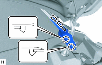
A bolt without a torque specification is shown in the standard bolt chart.
Click here .gif)
PROCEDURE
1. CLEAN WINDSHIELD GLASS
| (a) Clean the outer edge of the windshield glass with non-residue solvent. NOTICE:
|
|
.png)
2. INSTALL NO. 1 WINDSHIELD OUTSIDE MOULDING CLIP
HINT:
- Perform the following procedure if replacing the No. 1 windshield outside moulding clip.
- Use the same procedure for the other clips.
| (a) Install a No. 4 nose piece to an air riveter and then insert the mandrel part of a new No. 1 windshield outside moulding clip into the nose piece. |
|
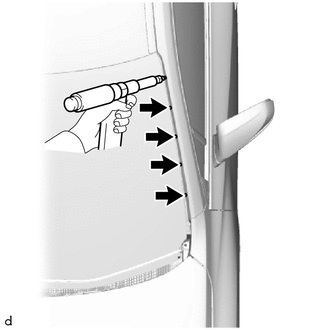
(b) Press the No. 1 windshield outside moulding clip against the installation hole perpendicularly and using an air riveter, install the No. 1 windshield outside moulding clip.
3. INSTALL NO. 1 WINDSHIELD GLASS STOPPER
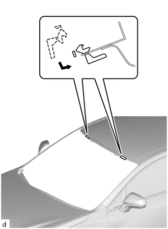
| (a) Install 2 new No. 1 windshield glass stoppers to the vehicle body as shown in the illustration. NOTICE: Only 2-piece type windshield glass stoppers are provided as supply parts. Use 2-piece type stoppers as replacements even if 1-piece type stoppers were originally installed. |
|
4. INSTALL NO. 2 WINDSHIELD GLASS STOPPER
(a) Using a brush or sponge, coat the application area of 2 new No. 2 windshield glass stoppers with glass primer.
NOTICE:
- Do not apply too much primer.
- Allow the primer to dry for 3 minutes or more.
- Throw away any leftover primer.
HINT:
If an area other than specified is coated by accident, wipe off the primer with a clean piece of cloth before it dries.
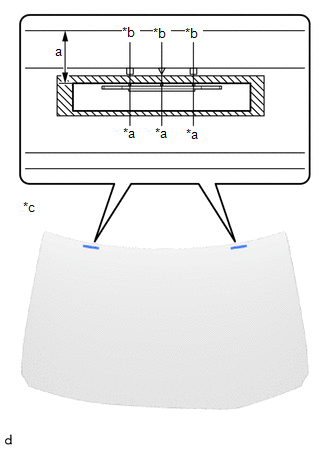
| *a | Center Line |
| *b | Ceramic Notch |
| *c | Back Side |
.png) | Glass Primer Application Area |
(b) Remove the peeling paper from the face of the No. 2 windshield glass stopper.
HINT:
After removing the peeling paper, keep the exposed adhesive free from foreign matter.
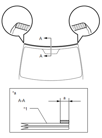
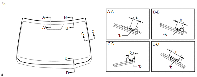
(c) Install the 2 No. 2 windshield glass stoppers to the windshield glass as shown in the illustration.
Standard:
| Area | Specified Condition |
|---|---|
| a | 16 mm (0.630 in.) |
NOTICE:
- Install the No. 2 windshield glass stopper after primer has been allowed to dry (approx. 3 min.)
- Make sure to install the No. 2 windshield glass stopper in the correct orientation.
5. INSTALL WINDOW GLASS ADHESIVE DAM
(a) Using a brush or sponge, coat the application area of a new window glass adhesive dam with glass primer.
NOTICE:
- Do not apply too much primer.
- Allow the primer to dry for 3 minutes or more.
- Throw away any leftover primer.
HINT:
If an area other than specified is coated by accident, wipe off the primer with a clean piece of cloth before it dries.
(b) Remove the peeling paper from the face of the window glass adhesive dam.
HINT:
After removing the peeling paper, keep the exposed adhesive free from foreign matter.
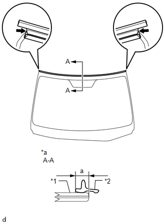
(c) Install the window glass adhesive dam to the windshield glass as shown in the illustration.
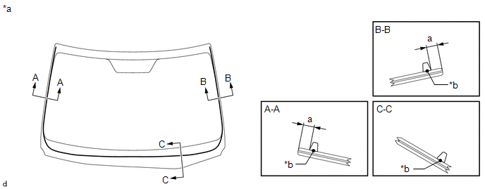
| *a | Back Side | *b | Window Glass Adhesive Dam Center Line |
Standard:
| Area | Specified Condition |
|---|---|
| a | 7.0 mm (0.276 in.) |
NOTICE:
Install the window glass adhesive dam after primer has been allowed to dry (approx. 3 min.).
6. INSTALL WINDSHIELD OUTSIDE MOULDING
(a) Using a brush or sponge, coat the application area of a new windshield outside moulding with glass primer.
Standard:
| Area | Specified Condition |
|---|---|
| a | 7.0 mm (0.276 in.) or more |
NOTICE:
- Do not apply too much primer.
- Allow the primer to dry for 3 minutes or more.
- Throw away any leftover primer.
| *1 | Windshield Glass |
| *a | Back Side |
| | Glass Primer Application Area |
(b) Remove the peeling paper from the face of the windshield outside moulding.
HINT:
After removing the peeling paper, keep the exposed adhesive free from foreign matter.
(c) Install new windshield outside moulding to the windshield glass as shown in the illustration.
| *1 | Windshield Glass |
| *2 | Windshield Outside Moulding |
| *a | Back Side |
.png) | R End |
Standard:
| Area | Specified Condition |
|---|---|
| a | 7.0 mm (0.276 in.) |
HINT:
Align the edges of the windshield outside moulding with the R ends and install it.
NOTICE:
Install the windshield outside moulding after primer has been allowed to dry (approx. 3 min.).
7. INSTALL WINDSHIELD GLASS
| *1 | Vehicle Body |
| | Adhesive |
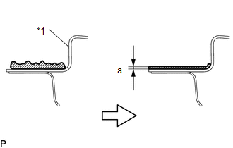
(a) Clean and shape the contact surface of the vehicle body.
(1) On the contact surface of the vehicle body, use a knife to cut away excess adhesive as shown in the illustration.
Standard:
| Area | Specified Condition |
|---|---|
| a | 1.0 mm (0.039 in.) |
NOTICE:
Leave as much adhesive on the vehicle body as possible.
(2) Clean the contact surface of the vehicle body with cleaner.
HINT:
Even if all the adhesive has been removed, clean the vehicle body.
| (b) Position the windshield glass. (1) Using suction cups, place the windshield glass in the correct position. (2) Check that the entire contact surface of the glass rim is perfectly even. (3) Place matchmarks on the windshield glass and vehicle body at the locations indicated in the illustration. NOTICE: Check that the stoppers are attached to the vehicle body correctly. (4) Using suction cups, remove the windshield glass. |
|

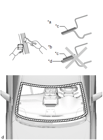
| *a | CORRECT |
| *b | INCORRECT |
| *c | Body Primer |
| *d | Adhesive |
| | Body Primer Application Area |
(c) Using a brush, apply body primer to the exposed part of the vehicle body.
NOTICE:
- Allow the primer to dry for 3 minutes or more.
- Do not apply primer to the adhesive.
- Throw away any leftover primer.
- Do not apply too much primer.
(d) Using a brush or sponge, apply glass primer to the contact surface of the glass.
| *a | Back Side | *b | Adhesive Center Line |
| | Glass Primer Application Area | - | - |
Standard:
| Area | Specified Condition |
|---|---|
| a | 8.0 mm (0.315 in.) |
| b | 11 mm (0.433 in.) or more |
| c | 19 mm (0.748 in.) or more |
HINT:
If the primer is applied to an area that is not specified, apply non-residue solvent to a clean cloth and wipe off the excess primer.
NOTICE:
- Allow the primer to dry for 3 minutes or more.
- Throw away any leftover primer.
- Do not apply too much primer.
(e) Apply adhesive to the windshield glass.
Adhesive:
Toyota Genuine Windshield Glass Adhesive (High modulus Type) or Equivalent
| *1 | Sealer Gun |
| *2 | Nozzle |
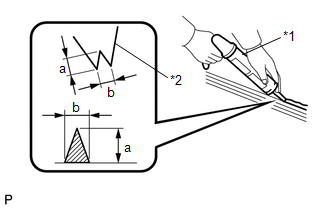
(1) Cut off the tip of the cartridge nozzle as shown in the illustration.
HINT:
After cutting off the tip, use all adhesive within the time written in the table below.
Standard:
| Area | Specified Condition |
|---|---|
| a | 12 mm (0.472 in.) |
| b | 8.0 mm (0.315 in.) |
Usage Time Frame:
| Temperature | Usage Time Frame |
|---|---|
| 35°C (95°F) | 15 minutes |
| 20°C (68°F) | 1 hour 40 minutes |
| 5°C (41°F) | 8 hours |
(2) Load the sealer gun with the cartridge.
(3) Apply adhesive to the glass as shown in the illustration.
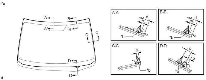
| *a | Back Side | *b | Adhesive Center Line |
Standard:
| Area | Specified Condition |
|---|---|
| a | 3.0 mm (0.118 in.) |
| b | 4.0 mm (0.157 in.) |
| c | 8.0 mm (0.315 in.) |
| d | 10 mm (0.394 in.) |
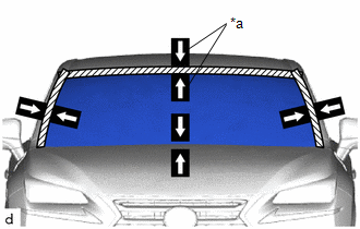
| (f) Install the windshield glass to the vehicle body. (1) Using suction cups, position the windshield glass so that the matchmarks are aligned. Press it in gently along the rim. NOTICE:
(2) Lightly press the outer surface of the glass to ensure that it is securely fit to the vehicle body. HINT: Press the glass with force of 98 N (10 kgf, 22.0 lbf) or more. (3) Using a scraper, remove any excess or protruding adhesive. NOTICE: Apply adhesive to the glass rim. (4) Using a scraper, remove any excess or protruding adhesive. (5) Hold the windshield glass in place securely with protective tape or equivalent until the adhesive hardens. NOTICE: Do not drive the vehicle for the time described in the table below. Minimum Time:
|
|
8. CHECK FOR LEAKS AND REPAIR
(a) After the adhesive has hardened, apply water from the outside of the vehicle. Check that no water leaks into the cabin.
(b) If water leaks into the cabin, allow the water to dry and add adhesive.
(c) Remove the protective tape.
9. INSTALL ROOF HEADLINING ASSEMBLY
(a) for Normal Roof:
Click here
(b) for Sliding Roof:
Click here
10. INSTALL ASSIST GRIP SUB-ASSEMBLY
Click here
11. INSTALL MAP LIGHT ASSEMBLY
Click here
12. INSTALL VISOR HOLDER
Click here
13. INSTALL VISOR ASSEMBLY LH
Click here
14. INSTALL RH VISOR ASSEMBLY
HINT:
Use the same procedure described for the LH side.
15. INSTALL VISOR BRACKET COVER
Click here
16. INSTALL FRONT PILLAR GARNISH ASSEMBLY LH
Click here
17. INSTALL FRONT PILLAR GARNISH ASSEMBLY RH
HINT:
Use the same procedure described for the LH side.
18. INSTALL FRONT DOOR OPENING TRIM WEATHERSTRIP LH
Click here
19. INSTALL FRONT DOOR OPENING TRIM WEATHERSTRIP RH
HINT:
Use the same procedure described for the LH side.
20. INSTALL AIR CONDITIONING THERMISTOR ASSEMBLY (HUMIDITY SENSOR) (w/ Humidity Sensor)
Click here
21. INSTALL INNER REAR VIEW MIRROR ASSEMBLY
Click here
22. INSTALL RAIN SENSOR (w/ Rain Sensor)
Click here
23. INSTALL FORWARD RECOGNITION WITH HEATER HOOD SUB-ASSEMBLY
Click here
24. INSTALL FORWARD RECOGNITION CAMERA
Click here
25. INSTALL FORWARD RECOGNITION LATCH
Click here
26. INSTALL NO. 1 FORWARD RECOGNITION COVER
Click here
27. INSTALL NO. 2 FORWARD RECOGNITION COVER
Click here
28. INSTALL WINDSHIELD OUTSIDE MOULDING LH
(a) Attach the claw to install the windshield outside moulding LH.
29. INSTALL WINDSHIELD OUTSIDE MOULDING RH
HINT:
Use the same procedure described for the LH side.
30. INSTALL COWL TOP VENTILATOR LOUVER SUB-ASSEMBLY
Click here
31. INSTALL FRONT FENDER TO COWL SIDE SEAL LH
(a) Remove the double-sided tape from the front fender sub-assembly LH surface.
NOTICE:
- Installing the front fender to cowl side seal LH with any double-sided tape remaining may cause poor adhesion. Therefore, perform this procedure until sufficiently removed.
- Make sure to use a cloth when removing. Using a screwdriver, etc., may cause damage and poor adhesion.
(b) Wipe off any tape adhesive residue with cleaner.
(c) Remove the peeling paper from the face of the front fender to cowl side seal LH.
HINT:
After removing the peeling paper, keep the exposed adhesive free from foreign matter.
(d) Attach the 2 guides, 2 claws and double-sided tape to install the front fender to cowl side seal LH.
| | Double-sided Tape |
NOTICE:
Press the front fender to cowl side seal LH firmly to install it.
32. INSTALL FRONT FENDER TO COWL SIDE SEAL RH
HINT:
Use the same procedure described for the LH side.
33. INSTALL FRONT WIPER ARM LH
Click here
34. INSTALL FRONT WIPER ARM RH
Click here
35. INSTALL FRONT WIPER ARM HEAD CAP
Click here
36. CHECK WINDSHIELD GLASS
(a) Conduct a leak test after the adhesive has completely hardened.
(b) Seal any leaks with auto glass sealer.
37. ADJUST FORWARD RECOGNITION CAMERA
(a) One time Recognition:
Click here
(b) Sequential Recognition:
Click here
READ NEXT:
 Components
COMPONENTS ILLUSTRATION *1 COWL TOP VENTILATOR LOUVER SUB-ASSEMBLY *2 FRONT WIPER ARM HEAD CAP *3 WINDSHIELD WIPER ARM AND BLADE ASSEMBLY LH *4 WINDSHIELD WIPER ARM AND BLADE ASSEM
SEE MORE:
Replacement
REPLACEMENT CAUTION / NOTICE / HINT HINT: There are 2 methods for brake fluid replacement: using the Techstream or not using the Techstream. NOTICE:
Perform fluid replacement with park (P) selected and the parking brake applied.
As brake fluid may overflow when replacing brake fluid, do not pla
Installation
INSTALLATION CAUTION / NOTICE / HINT CAUTION: Wear protective gloves. Sharp areas on the parts may injure your hands. PROCEDURE 1. INSTALL LUMBAR SUPPORT ADJUSTER ASSEMBLY LH (a) Attach the 2 hooks to install the lumbar support adjuster assembly LH to the front seatback frame sub-assembly LH. 2. INS
